I picked it up from my engine builder when I delivered the turbo.
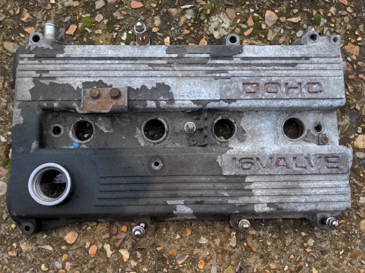
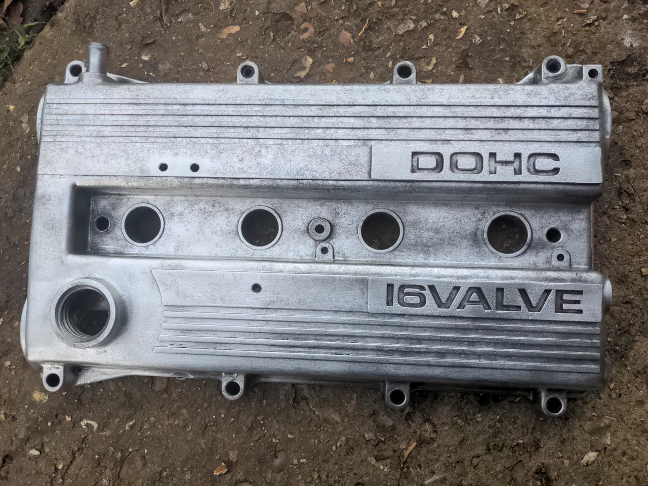
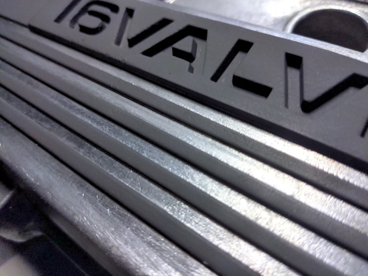
I shouldn't really file it under the "Rationalising" series. My rocker cover needed a new gasket and then would have continued to last forever, because they don't wear out. There was nothing to rationalise; it was neither badly modified nor badly designed. What it also was not, as even the indifferent will notice, was pretty.
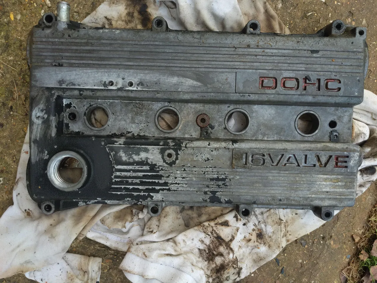
That's not mine; it is one beautifully restored by 80s Hero. I could have done exactly the same thing with mine, but the one above is perfect. Because it has been done perfectly, I can't do better than it, so instead I would have to do something completely different. I had an idea which I did not know would work or not, but if it worked as well as it did in my head it would be awesome.
But before I could do any of that, I had to remove nearly four decades of corrosion, flaky paint, and overcooked oil from it. Half a gallon of old petrol, some oven cleaner and a pressure washer got it back to this...
I could have had this vapour blasted instead of cleaning it myself, manually. I didn't mostly because I started this a few days before Christmas when everything was closed, and partly because I started this a few days before Christmas and needed something to keep me out of trouble in my time off. But I happen to like that this preserves some of the "texture" of the aluminium. Other people have done the ultra-shiny mirror-finish engine bay to perfection; again, because I can't beat that, I have to do something different instead.
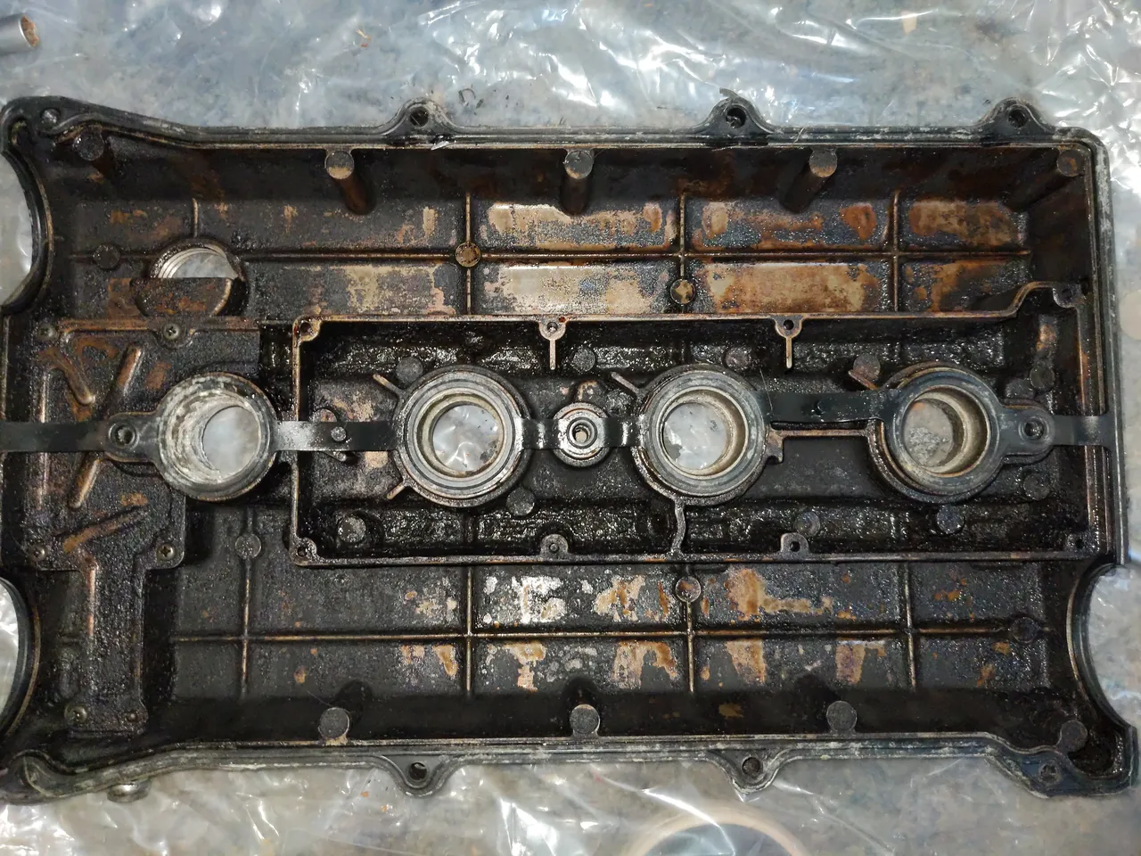
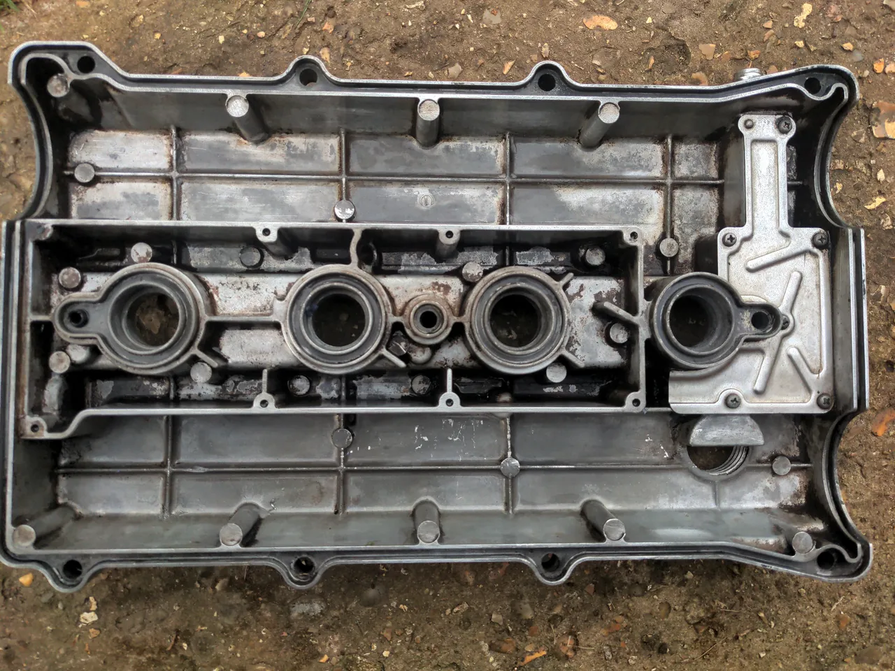
After all that, the underside didn't look quite so toxic either.
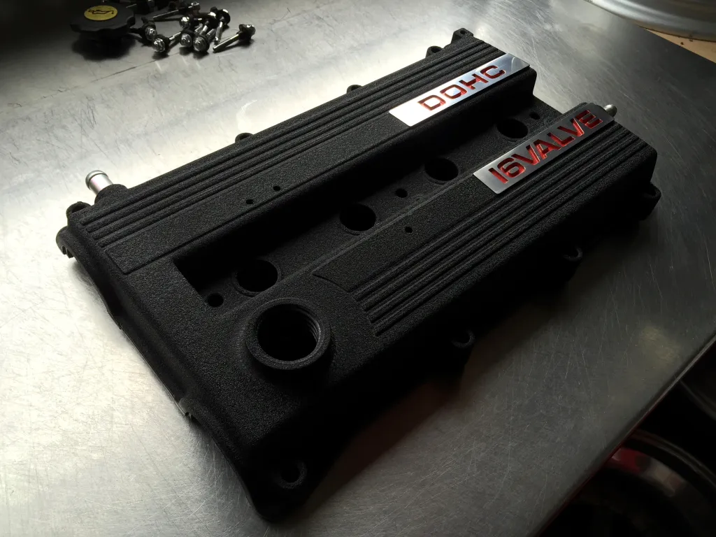
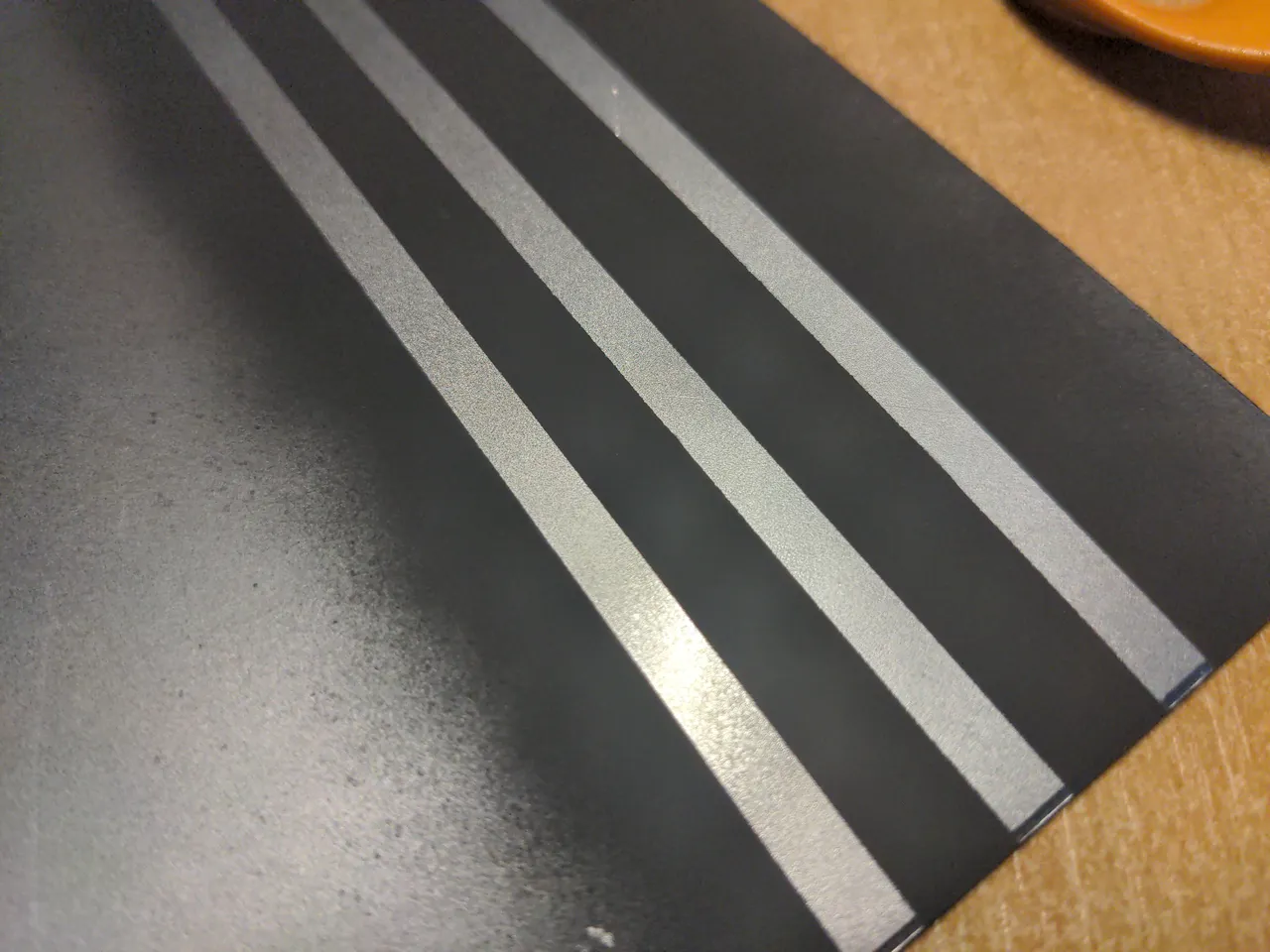
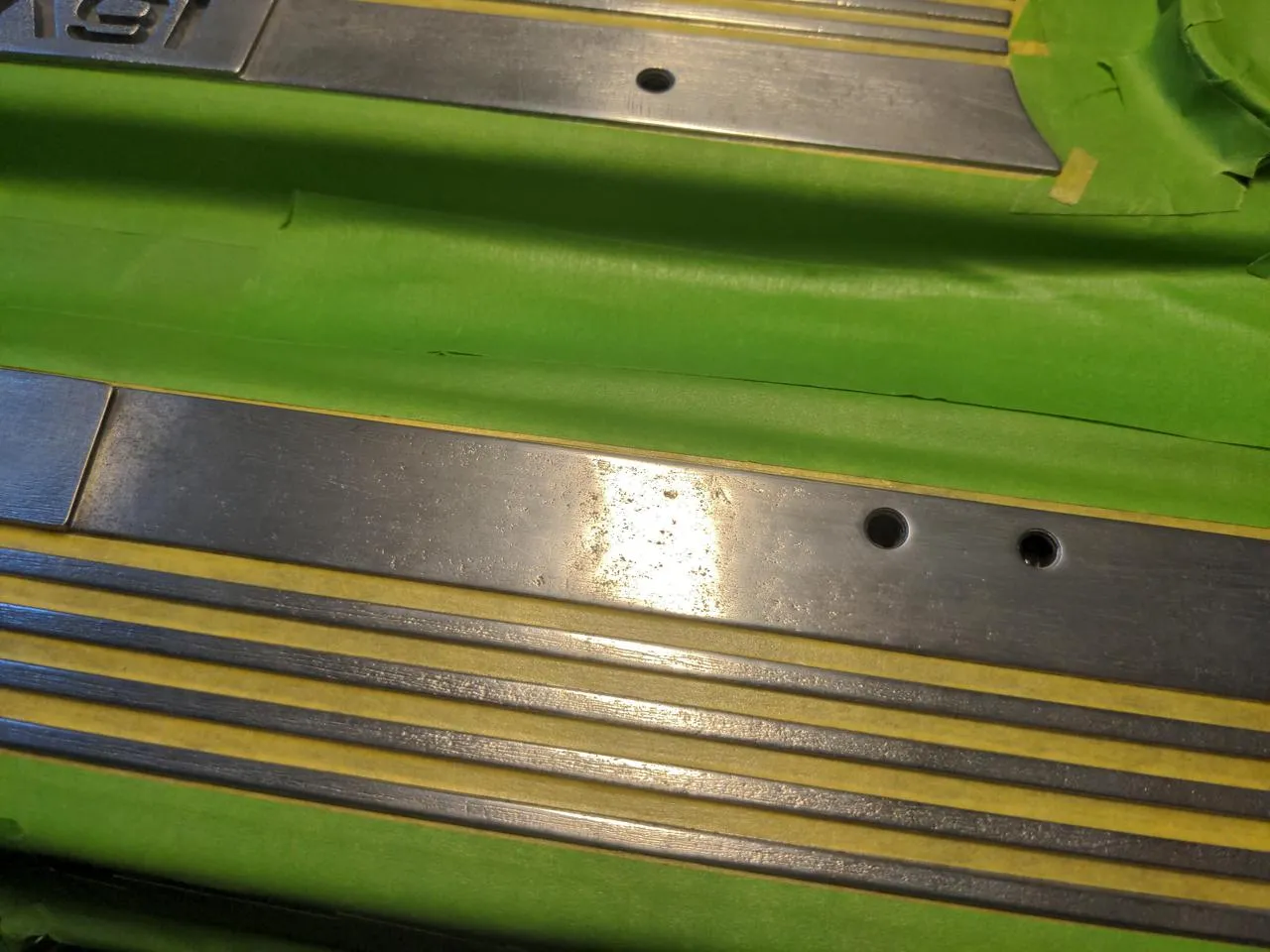
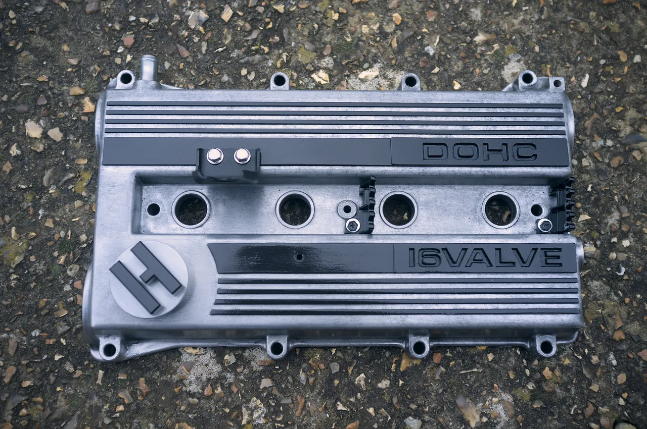
Back to the plan that was in my head! That plan was to mask off everything but the raised parts, spray those black, then unmask it and clear-coat both the painted and unpainted parts. For the fine bits of masking, I tested with 4mm and 5mm Hobby 2000 tape, which is designed for scale modellers. I figured they really like sharp lines in that world, but to be sure that it would work with the paint I was using I did a test on a sheet of clean brand-new steel plate I had kicking around.
...then gave it a couple of coats of Jenolite matt BBQ paint, as previously seen on my heat shield. I didn't use this paint for its temperature-resistant properties; if it ever got close to 650 C at the rocker cover I would have bigger things to worry about than my paint coming off, such as my engine being violently on fire. Rather, that was the matt black paint which I had kicking around, so I used it.
That required baking (in the big BBQ this time round) to make it cure, and then I lacquered it with Jenolite clear coat. Which I'm not going to show you yet!
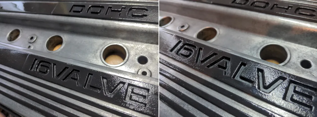
Originally, as you can on 80s Hero's beautiful rocker cover, the lettering would be red. I actually did this on the first iteration of the rocker cover (never believe that I get stuff right the first time), and I didn't like it. Instead, I decided on something more subtle, which was to paint in the letters in a slightly different black to make it recede a little.
It is subtle! So subtle that I'm not sure it actually made any difference other than in photos with a light carefully angled to show the difference - let alone from the 10 feet or so away that anyone but me will ever see this. But I know it is there!
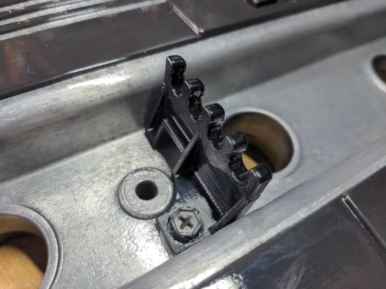
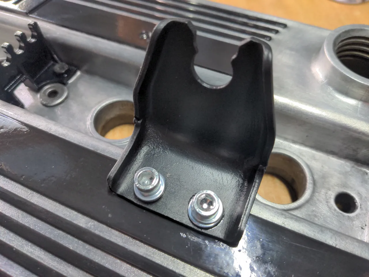
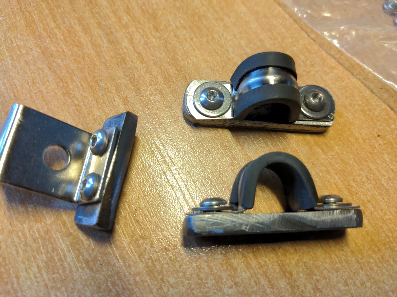
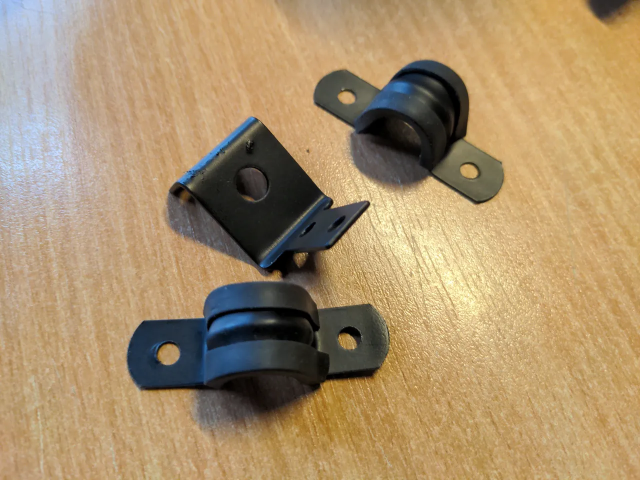
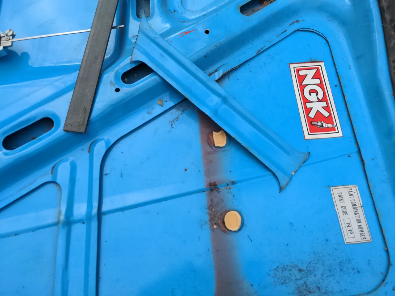
One of my HT lead separator thingies was broken. It's on the right of the original picture above. You probably won't see it, because it was broken.
Fortunately, these are identical to the ones fitted to the early 1.6 MX5s. That means I can buy reproductions of them. I could probably find genuine ones if I was more patient, but these were available immediately. I think they are 3D printed. They are not as strong as the originals; I broke one while mishandling the rocker cover.
So I didn't. It got attacked with a wire brush and then sprayed with Jenolite satin black paint. (I love Jenolite paints! I mention them often enough that you'd think they sponsor me; I use enough of their paint that I wish they would.)
It bothered me that I used the wrong bolts in this pic. I thought allen heads would look neater, then after I had torqued them down didn't like how they sat. I replaced them with M6x16mm flanged bolts almost immediately after I took the photo.
There was nothing wrong with it. If there was, these are one of the parts shared with the MX-5; I can buy as many of those as I want! And that would look better than most of the aftermarket ones. They're too blingy and branded, which is not at all the look I wanted for my engine bay, because I'm not obsessive about minor details while simultaneously having a blindspot for the big important things at all.
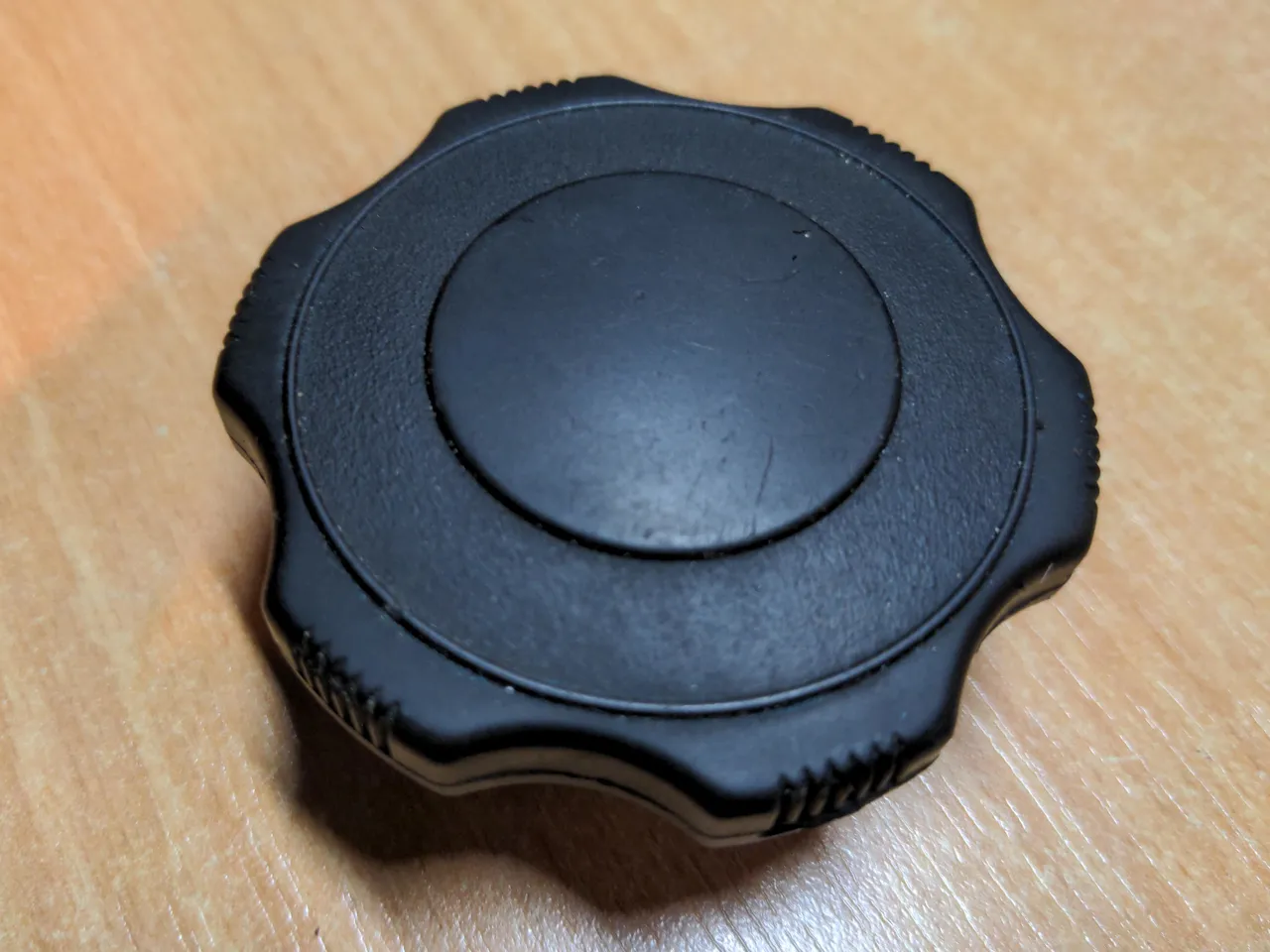
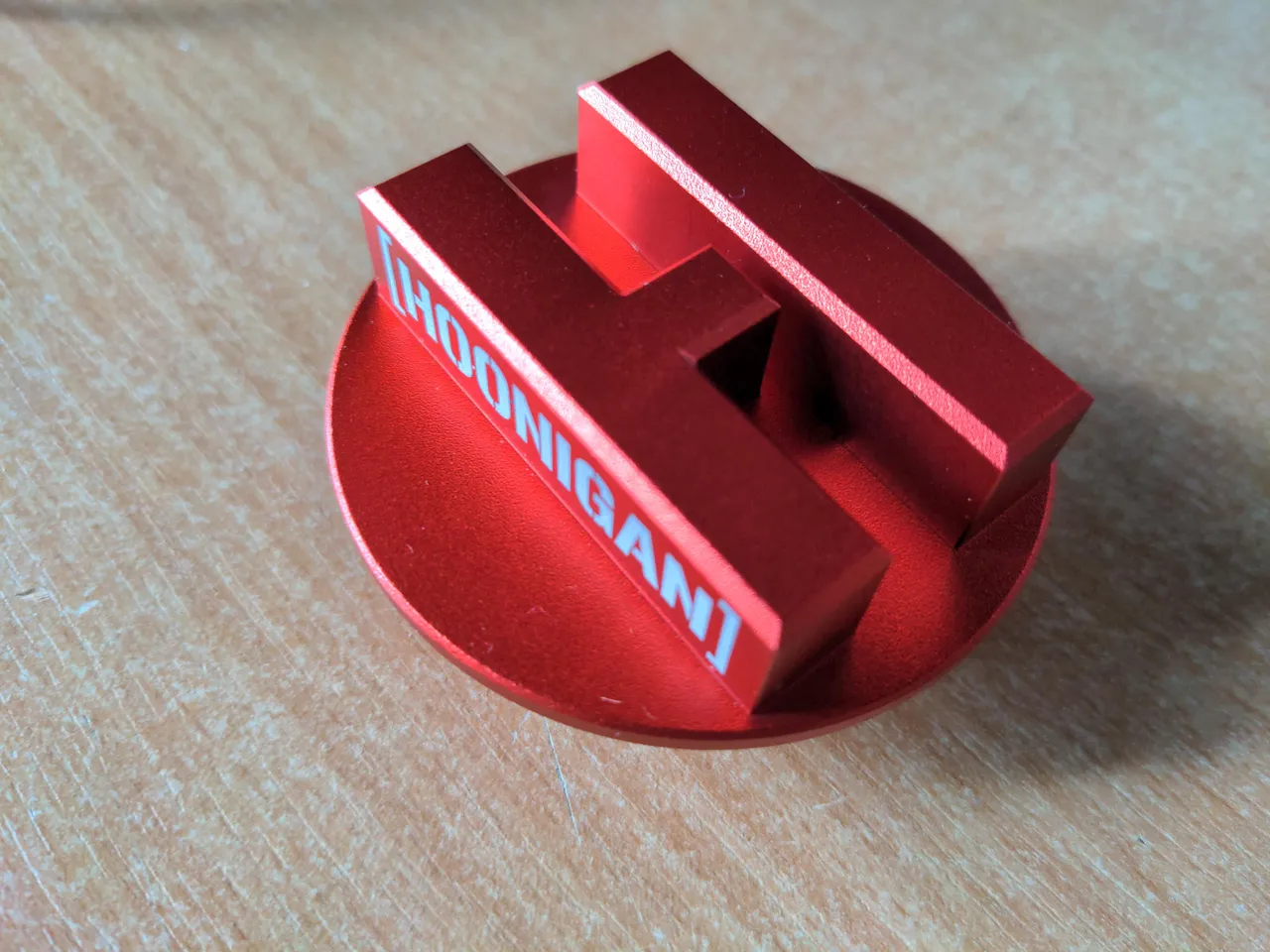
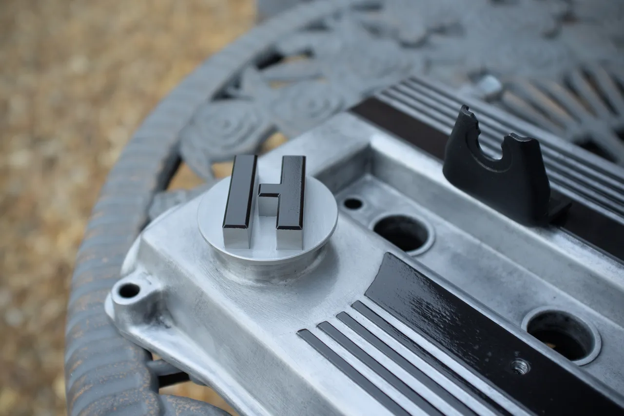
I almost liked the Hoonigan-by-Mishimoto filler cap.
Which is blingy and branded! But it has a nice shape, which meant I could do something with it. So I bought it, and had the red anodising blasted off it by my local powder coaters. And then, to match the rocker cover, I masked off everything but the top face and the 45 degree chamfer on the corner, painted that black with the same Jenolite matt black BBQ paint, baked it...
Or at least, I have one that doesn't look like anybody else's, and one that turned out exactly the way it did in my head when I first had the idea. And minus the silly overkill oil cap all of this probably would have cost me about 50 quid even if I wasn't using materials which I already had.
Next!
Part numbers from this post
4mm masking tape: Hobby 2000 H2K80007
Green masking tape: Frog Tape 155874
Black high-temperature paint: Jenolite 89096
Clear coat: Jenolite 88987
Satin black paint: Jenolite 89510
Oil filler cap: Mishimoto MMOFC-MAZ-HOONRD
HT lead separator thingies: Mazda B660-10-241 (unavailable)
All of my neighbors are all up in arms
About something they saw on TV
Some politician got busted for something
That won't make much difference to me
Now I'm sure it's all true and I'm tired of this too
But I can't pray for some guy to fall
I say let all these people do what all these people do
I'm just happy to be here at all
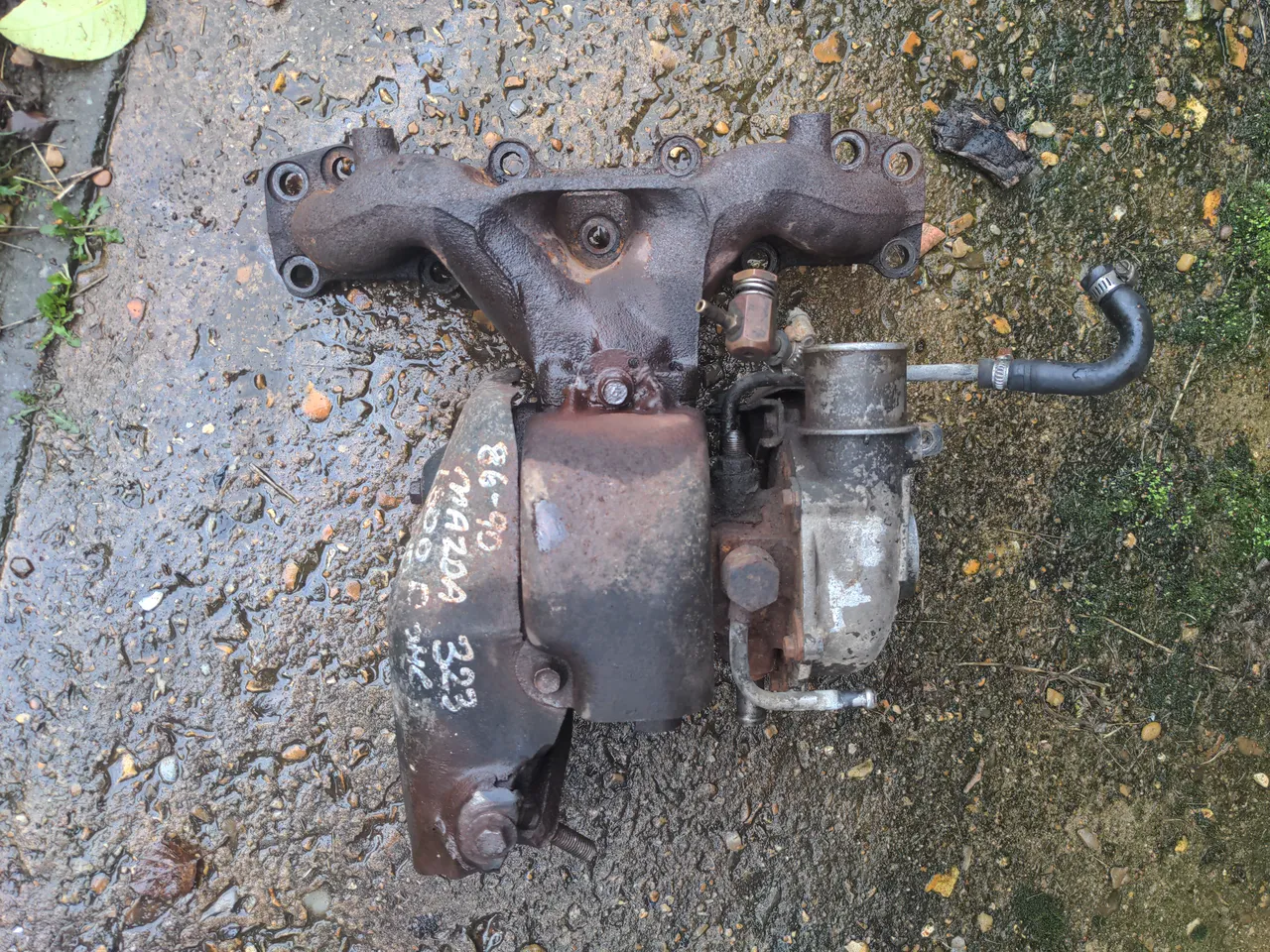
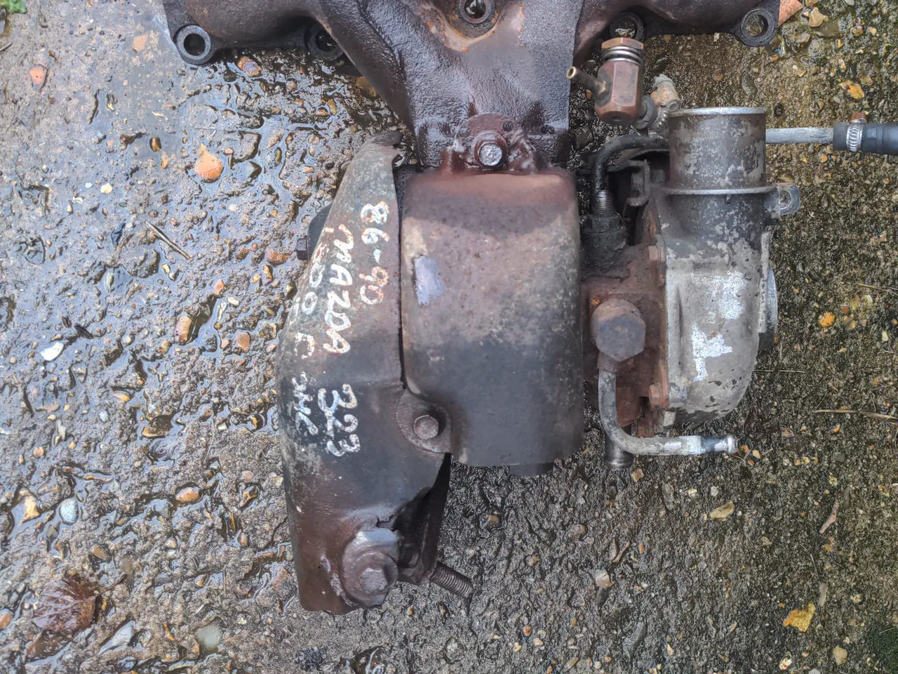
It is an IHI VJ9, and it is also ancient worn-out junk that cannot be fixed.
The VJ9 is a tiny turbocharger built on the IHI RHB5 frame. Despite its size, it is ridiculously laggy compared to a modern turbo of the same size. I came to love that in the few months I had it on the road; a mildly-lively 16v engine that transforms violently into a howling turbocharged rally car engine at about 3500 RPM is hilarious.
This is actually the second turbo that has been fitted to this car. Back when my brother owned my 323 GTX, the original turbo was so worn out that the car spewed enough white smoke to be an actual danger to other road users, so he used his superpower of finding car parts that do not exist to acquire a "good" spare.
"Good" is in quotes, because it was still worn out; there was slack in the shaft, just not a quarter-inch of it like the old one, and the car did not spew smoke after the turbo was swapped. It was sure to be another failure in the near future, and re-fitting this to a freshly-rebuilt engine seemed insane to me.
As I found out, replacing or rebuilding this turbo has some pitfalls: there are no replacement VJ9s, there are no spare parts, and nobody will work on them.
1. There are no replacement IHI VJ9s.
They're gone; as far as I know they were only fitted to the Mazda 323 GTX, and only outside of the US. US models of the GTX had a slightly different VJ14 on the same RHB5 frame; the US models of the GTX made somewhat less power, so I shall assume the US turbo is worse. Occasionally one spots a used VJ14 out there, but that might well be a worse turbo than the VJ9 and there's no guarantee that it would have been a straight fit anyway.
The obvious answer is to have my current turbo rebuilt, which brings us to...
2. There are no spare parts.
I shipped my turbo to who I consider the best turbo company in the country - for turbos that are not obscure ones fitted to extremely obscure cars, anyway. The report back was that the turbo was actually completely shagged:
The bearing housing has damaged ring lands and the actual internal sleeve has separated – not reusable.
Turbine shaft has heavy journal wear – not reusable.
Seal plate has excessive ring land damage – not reusable.
Turbine housing has multiple cracks around the wastegate seat and volute – will go again with some processing.
Compressor housing has rub damage – will go again with some processing.
...and as I soon found out, none of the parts required exist anywhere; there was a multi-month delay getting my turbo back while aforementioned best-in-the-country turbo company scoured all their sources for some stash of parts that we all hoped existed, and did not exist.
3. Nobody will work on them
I know; I've tried. Any company in this country whose website claims they will rebuild a VJ9 will not actually rebuild a VJ9, and I know this because I have called all of them. Most likely some SEO geniuses thought that generating a page saying "we can rebuild X!" for each X of every possible turbo in the world would generate business for companies, rather than generate a small amount of wasted time for all concerned.
A rebuild was not going to happen, then. The only other option while maintaining a bottom-mount setup would have been to get a hybrid turbo. That, to simplify a lot, means preserving some part of the outer shell of an existing turbo and shoving completely different internals inside it. Nobody is willing to do this in this country, either; the few people who actually got back to me told me that it outright was not possible to do this with a VJ9.
What, then, of options that didn't maintain the bottom-mount setup? Turbo manifolds are available for the early 1.6 litre MX5s. I like the Walton Motorsport one, but cheaper options are available if you like playing "will it disintegrate" roulette. One of those turbo manifolds would bolt right up to the B6T's cylinder head; the B6ZE in the early MX5s is almost a B6T with the turbo removed. But I don't like this for a few reasons:
It would mean re-routing the exhaust and intake. Doable, but that would have to wait for the car to be in my possession again.
These manifolds are designed for the MX5; they work with the clearances and constraints of the MX5 engine bay, which mounts 90 degrees out from how the B6T fits in to the. Though the exhaust manifold might bolt up, there is no guarantee at all that that I would actually have space for it with any given turbo attached.
Mazda might have gone with a bottom-mount setup for a good reason. I don't know for a fact that they did, because I cannot give you any of those reasons, but I also don't know that they did not. I default to assuming that any major manufacturer knew what they were doing given the technology available at the time, and do differently if I know better.
Any of those things could have added months and unknown expenses to the project. But there are no bottom-mount turbos. Now what?
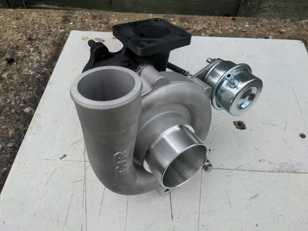
You may have noticed that I qualified an earlier paragraph about hybrid turbos with "in this country". Fortunately, nobody has told Bryan Nickell from BNR Supercars that it is not possible to build a VJ9 hybrid, because he has been doing this for years. Actually, he's been doing this with the US-market VJ14s, but the VJ9 is similar enough in the bits that matter to make it possible to do the same conversion.
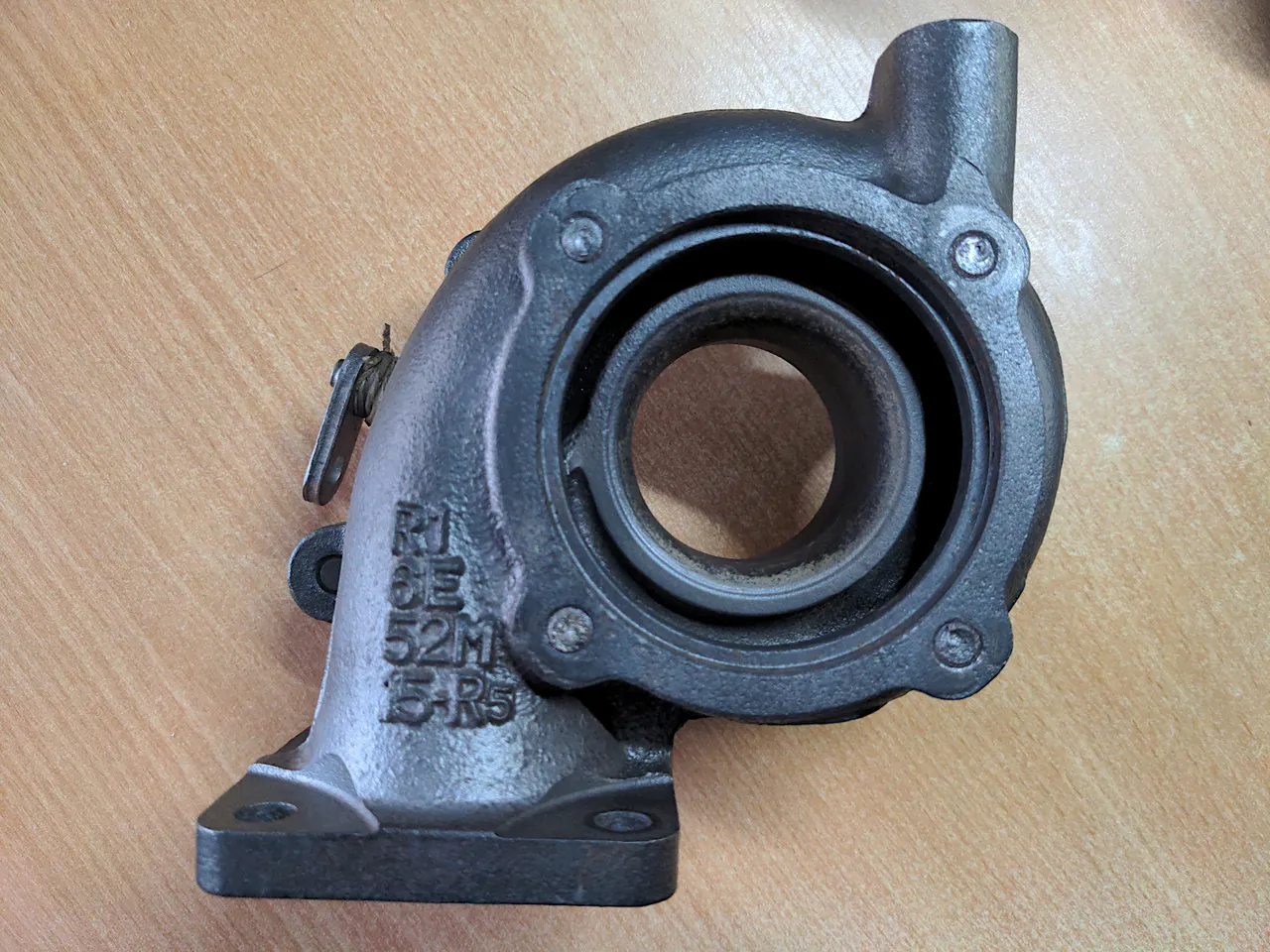
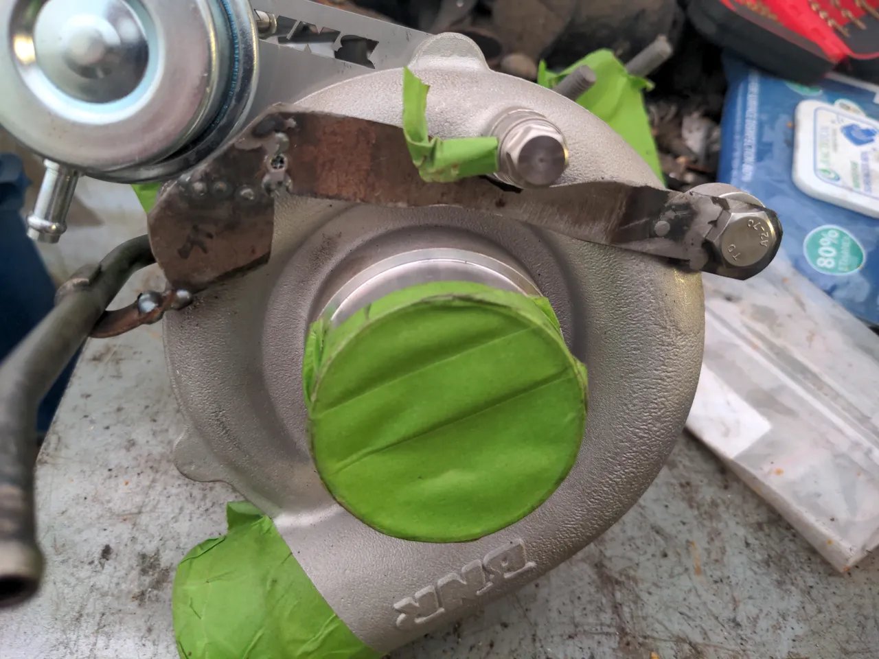
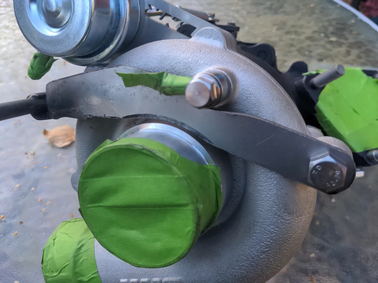
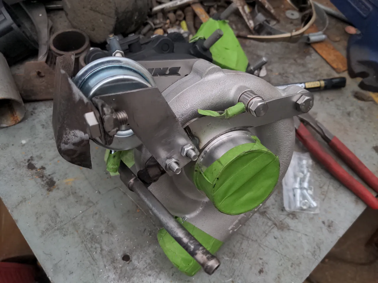
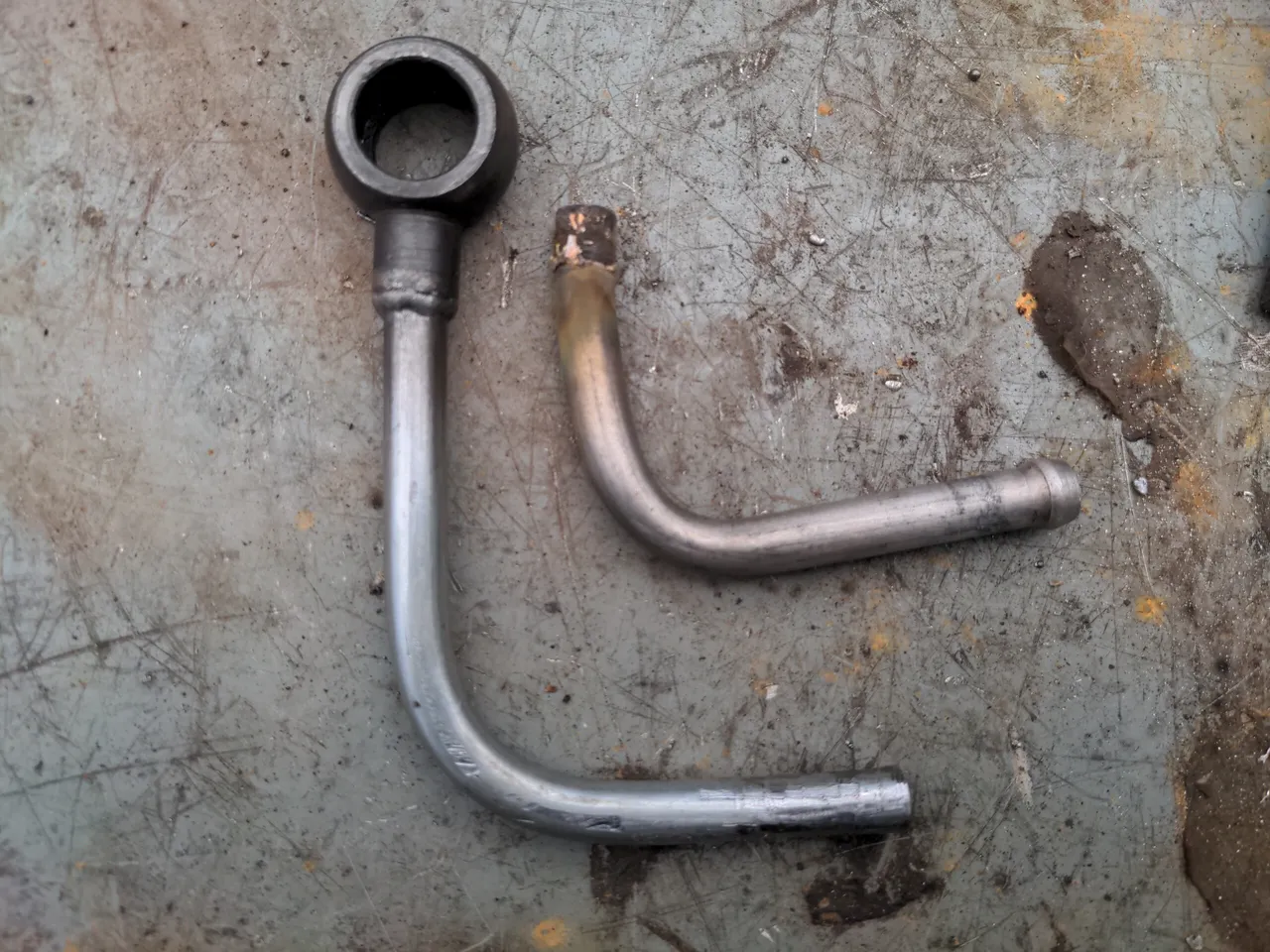
So, backtracking. The first pic is the turbine housing, and just the turbine housing. This bolts up to your exhaust manifold on one end, and bolts up to your downpipe on the other. Preserving this means that fitting this turbo does not require any modifications to the exhaust system; it stays as a bottom-mount turbo, bolting up to your original exhaust manifold and exhaust.
The rest of the turbo is thrown in the bin (don't actually do this, you'll need at least the compressor housing later as a reference for building pipework), and in its place you get a Garrett GT2860 CHRA with 360° thrust bearing, a much bigger compressor housing, an upgraded wastegate actuator, and a ported wastegate to avoid boost creep. Or, in other words, most of a modern Garrett GT2860 shoved inside half of an IHI VJ9!
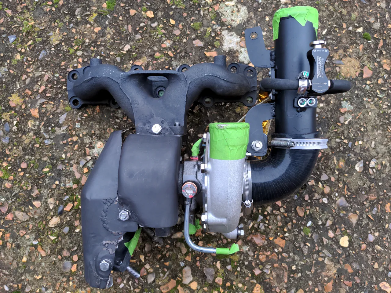
All of that is balanced meticulously, turning a worn-out turbo that was never very good even when new into a modern, reliable turbo good for about 330 horsepower (which is about 130 more than I care to have, but I like having the option). This completely rules!! And it allows me to keep the bottom mount setup, with the same exhaust manifold & downpipe, and the same water and oil feeds. So all that was left was to just bolt it all together, and
JUST KIDDING THAT NEVER HAPPENS
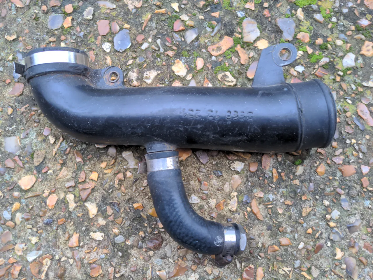
Of course I knew that it was not going to be that simple. The cold-side intake of the new turbo being substantially larger than the VJ9 rather guaranteed that. So let's start with this intake pipe.
I can't modify this pipe, because it is made of plastic. Well, I could; that wouldn't be that much worse than at least one of the modifications I have seen in this engine bay (clue: it is in the photo above). But half of the rationalisation project is to remove bad modifications, and I do not want to add another.
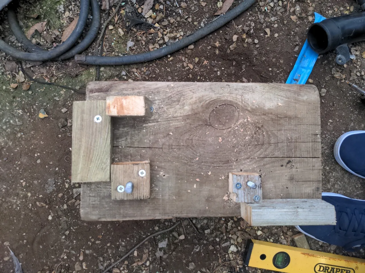
Finding someone who could fabricate a new intake pipe for turned out to be harder than it sounds (and this resulted in another multi-month delay), so I decided I might as well try and make it myself out of steel. And that starts with this:
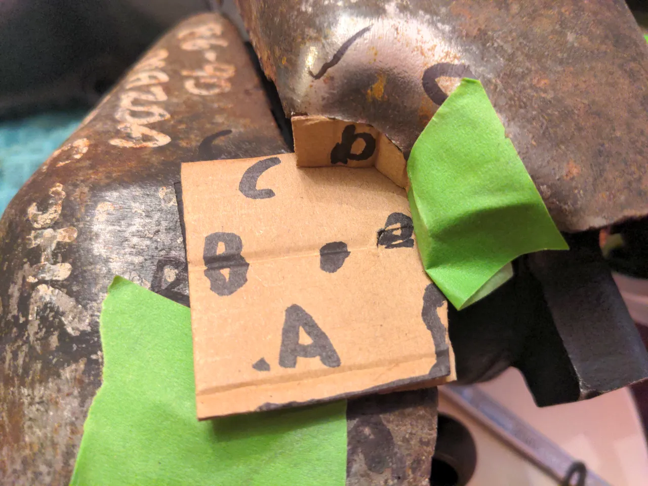
It marks out the rough locations of the inlet and outlet of the pipe, and it has some exhaust studs screwed into the wood which mark the location of the bolt holes. Some more pieces of wood mark the inlet and outlet of the pipe. All of this allows me to line up a piece of pipe (I happened to have an offcut of exhaust tubing which was exactly the right diameter for the job), and make some mounting points out of cardboard:
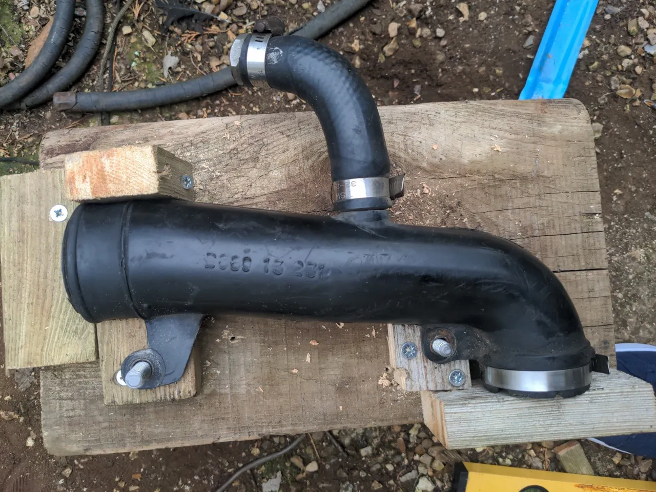
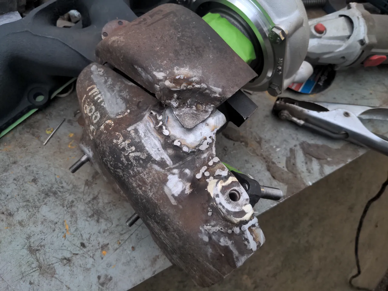
Those get made into 1.2mm steel with an angle grinder and welded on, and with a 90 degree silicone hose bend attached and a bit of Jenolite satin black paint...
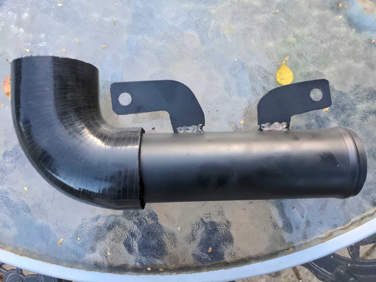
...I have an intake pipe! And yes, I know those mounting points look like they are not fitted straight; I sacrificed this to get the mounting angle perfect. You'll live.
You may have noted the nice bead on the end of that pipe. I made that with a £70 hand-cranked bead roller. That was not a bad investment. It's easy to use; even I got it more-or-less right on my second attempt.
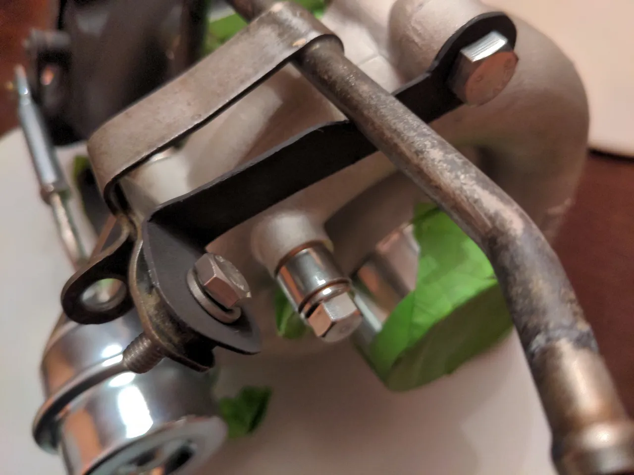
That mounting point does not exist on the new hybrid turbo. This bracket might have been overkill and I considered doing away with it altogether, but again I just assumed Mazda knew what they were doing when they did this, so made a prototype adapter bracket to go onto a mounting point on the compressor housing:
But after giving it some thought, I realised this would put the water pipe in the wrong orientation; it would feed from the correct side, but it would feed water up into the turbo, rather than down. That would be fighting gravity, which isn't such a big deal, but because it was fed from a completely different place, further modifications would be required on the engine side of all of this to make it work. I didn't want that, so I rethought it, chopped off the bracket from the water pipe, and welded on this crude prototype bracket made out of some 1mm scrap (also, see if you can spot where I forgot to turn on the MIG welder's gas)...
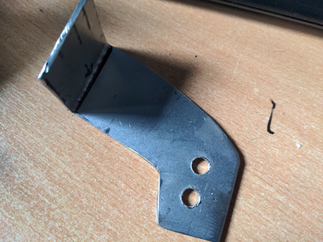
...I could incorporate that into the assembly, by making another 2mm steel bracket to bolt on to it via some M6 captive bolts welded on to the water pipe bracket.
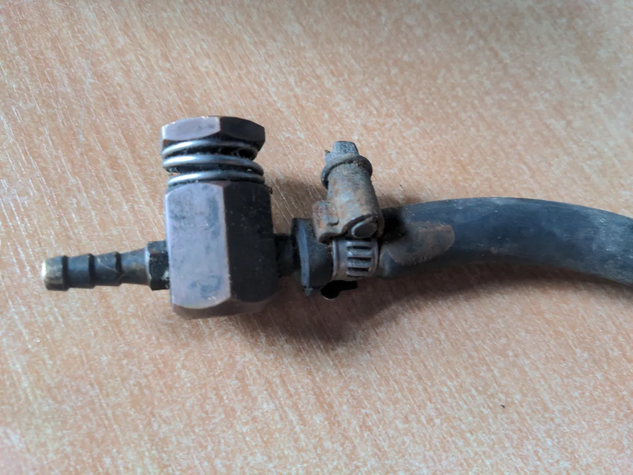
I put "boost controller" in quotes. My brother doesn't like it when I call it a boost controller; he insists that this is merely a bleed valve, and so I call it a boost controller to annoy him. It bleeds off air pressure to the wastegate, which means that the wastegate opens at a higher boost pressure. This is a very cheap way to run more boost in a turbo car. This did the job; it meant the 323 GTX was running about 13 psi, which with some calculations I completely made up would make it run about 200 horsepower.
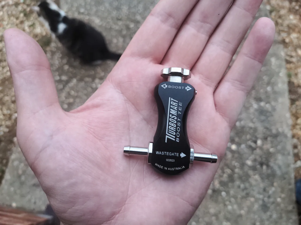
Still, I didn't like this boost controller, which is why I put it in quotes. It dangled around the engine bay not attached to anything but its hoses; thus, it was a bad modification. So I spent a few quid on a new Turbosmart Boost-Tee manual boost controller, which probably does the same thing, but looks much better.
This controller came with a bracket to attach it somewhere, and I was not entirely sure where when I bought it. Most people would just shove it into the bodywork with self tappers or cable tie it somewhere; if I did that, it would be another bad modification. Instead, after looking at my nice new intake pipe I figured attaching it there might be a good idea. So I did!
I took a 5mm-ish-thick section of angle iron, chopped it into smaller bits of steel, drilled and tapped some M4 threads into it...
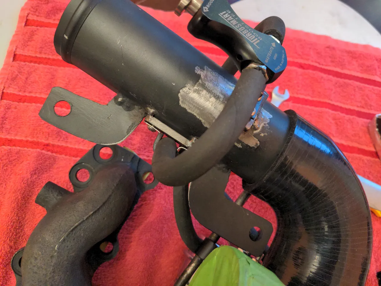
But, it bugged me that the boost controller bracket and the pipe clamps were shiny stainless steel, so I fixed that too, not that I am obsessed about tiny details or anything.
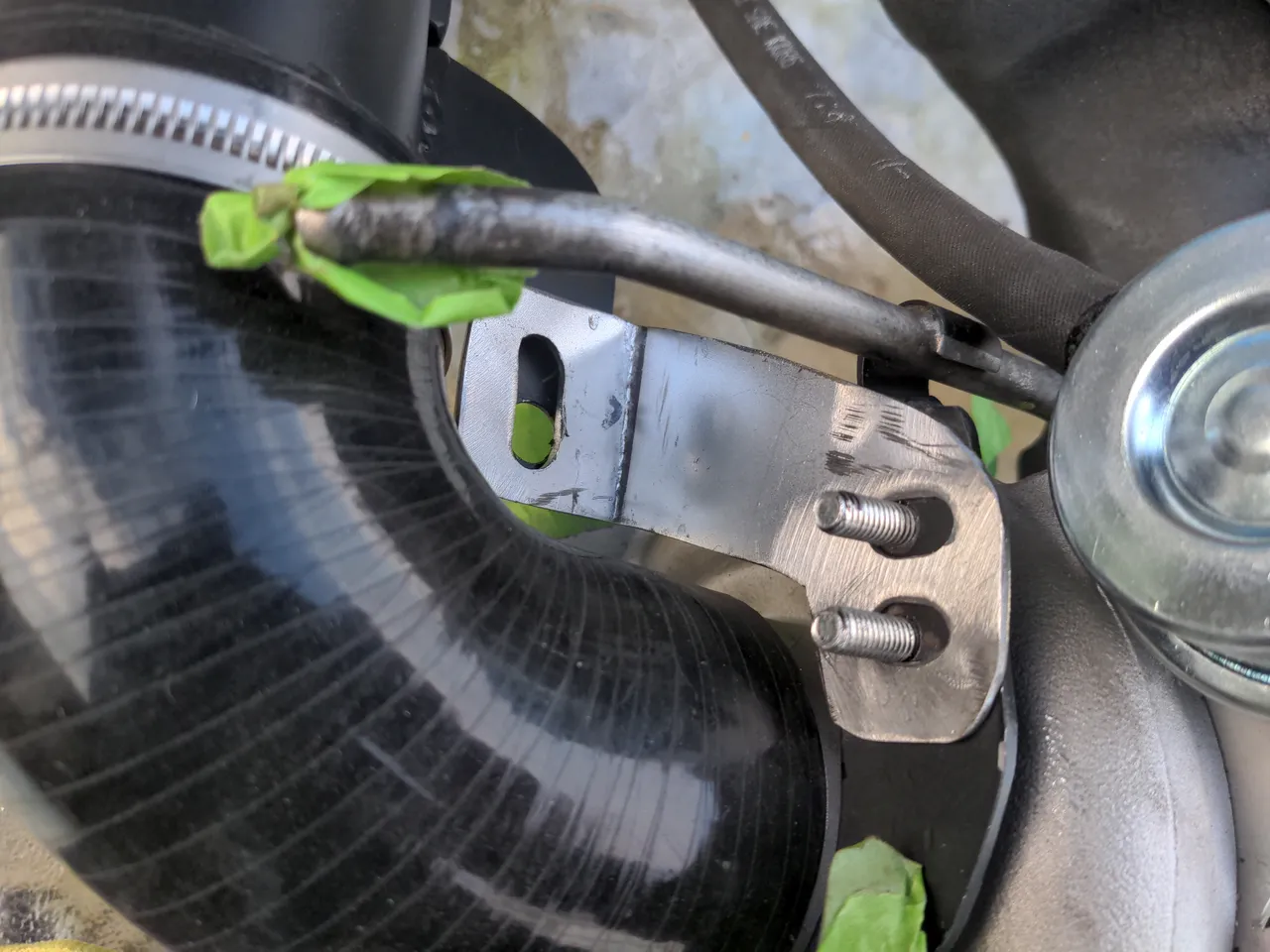
And then I modified the wastegate actuator heat shield bracket to add a routing guide for the pipe, which is to say, I drilled a hole in a piece of steel and welded that on to it.
You may notice that the water pipe is uncomfortably close to the intake pipe. You'd be wrong, because it's actually touching, which is more than uncomfortably close. We'll fix this later!
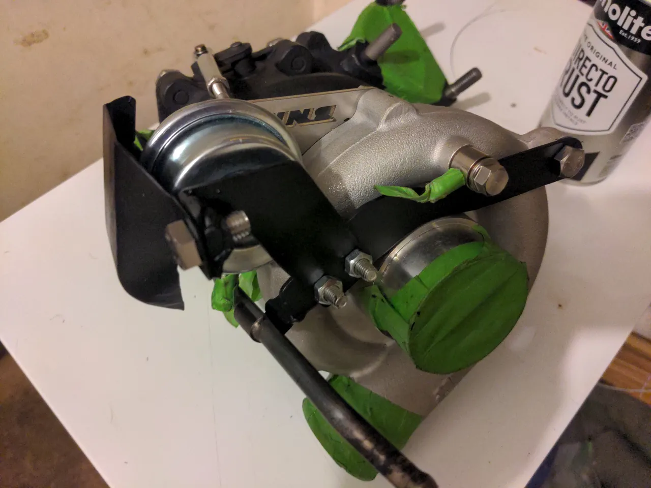
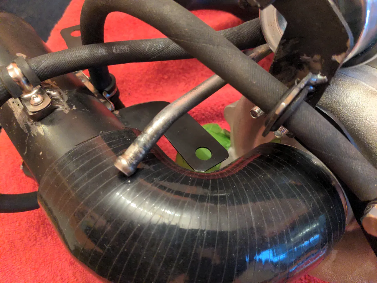
Back to our intake pipe. Here is a photo of it, in case you forgot what it looks like.
The mounting point on the right hand side on this photo bolts onto the engine somewhere. The one on the left used to bolt on to the turbo, on a mounting point that no longer exists. Which is OK, because we can add another bracket to our combined water pipe & wastegate actuator heat shield bracket to make a three way bracket!11
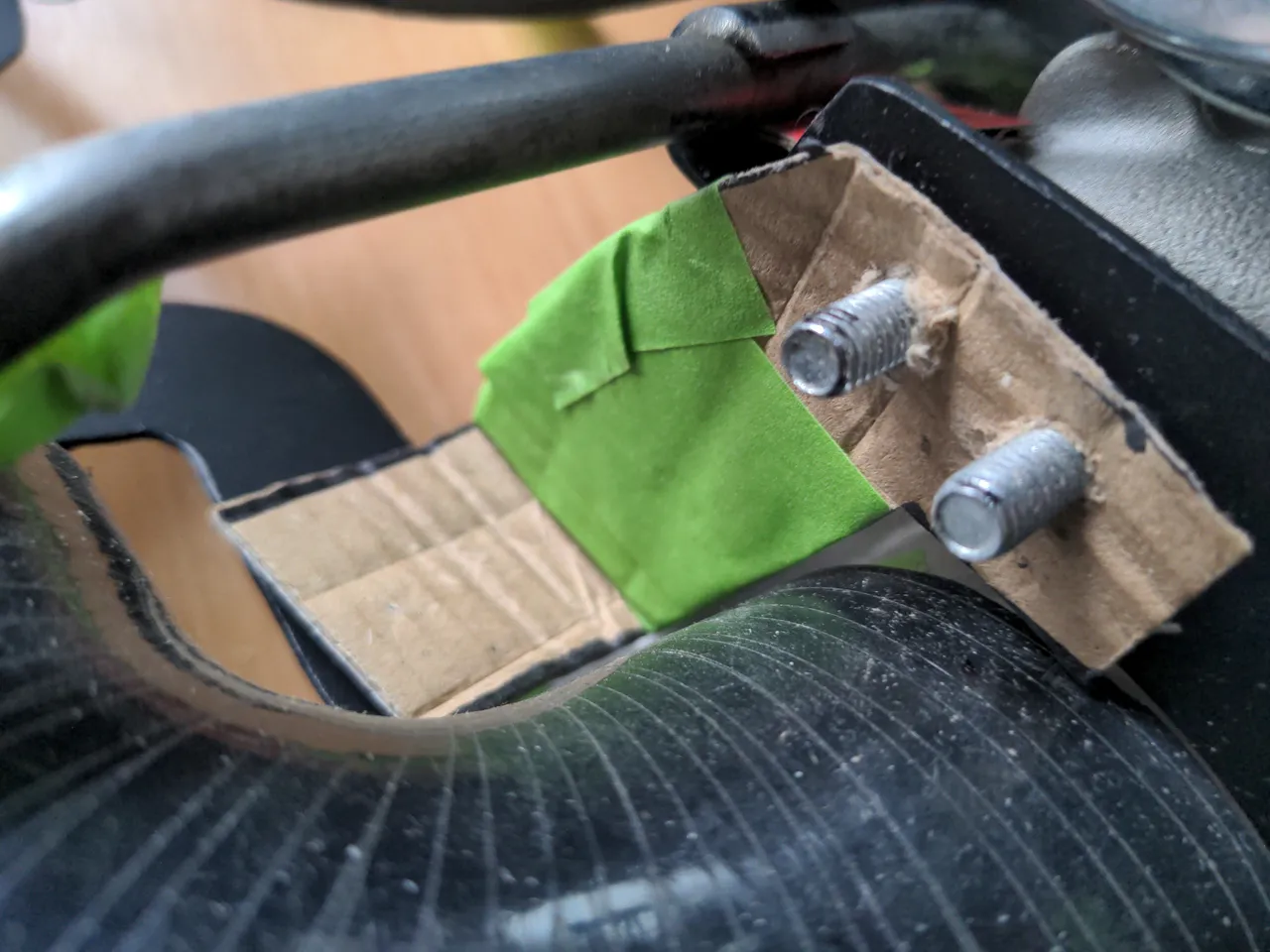
That means making a rough template out of a previously-unseen proprietary composite material (Frogtape-reinforced cardboard)...
If you didn't notice (and also if you did), the holes here are slotted on opposite axes (and doing this burned out my Ryobi multi-tool; lesson learned). This is because I am working blind, without the car; while I have taken as much care as I can to get this intake pipe dimensionally compatible with the original, I still don't know anything for a fact. With the combination of these slots, the flexible 90 degree bend, and the flex in the mounting points (the reason I made them out of 1.2mm steel!), this should have enough adjustment to fit on the car even if I got it completely wrong, which I don't think I did.
And now, some odds and ends, which happened at various points and didn't really fit into the narrative.
The downpipe and exhaust manifold were ceramic coated by my local powder coaters. This is an extremely high-temperature coating that should keep the heat in the exhaust system and out of the engine bay; as said previously, I am quite serious about heat management this time round.
This could be great, or it'll lock the heat into the cast iron and cause it to fail spectacularly. We will see!
Talking of the exhaust manifold, several of the studs did not come out cleanly. I cut these off, and re-drilled them. But I made two huge mistakes. One of them I re-drilled ever so slightly away from where it should have been - maybe three quarters of a millimetre, which took it out of tolerance and meant that the turbo did not fit on it. With another of these, the hole clearly needed helicoiling, and I made the mistake of not using a drill press when drilling it out for the helicoil. I figured the existing hole would guide me well-enough to be able to do it with a hand drill, and no it did not guide me well-enough; the hole for the helicoil was not made straight, and this meant the stud did not go in straight.
I thought this would be a write-off for the manifold, because nobody wants to fix 36 year old cast iron. Except Matt from Fusion Fabrications! Who drilled all but one of the holes out to 12mm, forced in some cast iron bungs, then meticulously re-drilled all the holes at the correct spacing.
Back to that water feed pipe from earlier. This only needed a tiny modification to get it to clear the much-larger intake pipe; I heated it up with the oxy-propane torch, and bent it in the other direction using two long sockets either side of the original bend.
The oil drain should have been a straight bolt-on fit. The Garrett CHRA was drilled to have them as two M6 holes spaced 38mm centre-to-centre. This is the correct spacing for every RHB5 turbo. But the drain from my VJ9 was spaced at 40mm for no reason, because why wouldn't you randomly have one turbocharger in a range of turbochargers with a subtly different oil drain?? Which means, it does not fit. So, the holes on the original oil drain had to be slotted 1mm inwards (thanks Maurice).
The turbo itself is a massive upgrade. The ceramic coatings & improved heat shielding should also be a substantial upgrade, and the new boost controller is not a bad modification like the old one was. And it looks a whole lot less ugly, though it is likely that nobody but me and my engine builder are ever going to see any of this.
More than anything, though, this has been a massive confidence boost for me. After having so many supplier delays (accounting for about nine of the thirteen months when you factor in people who gave me radio silence), I figured I'd take a punt at doing as much as I could of the work myself, such as the brackets & pipework & boost controller mounting. In one case doing it myself didn't work out; I should not have taken such a cavalier approach to the exhaust manifold studs, and I am thankful for Matt for fixing my mess. But sometimes it actually worked out fine! The pipework & brackets work well enough, and that was mostly just me and an angle grinder and a worn-out MIG welder.
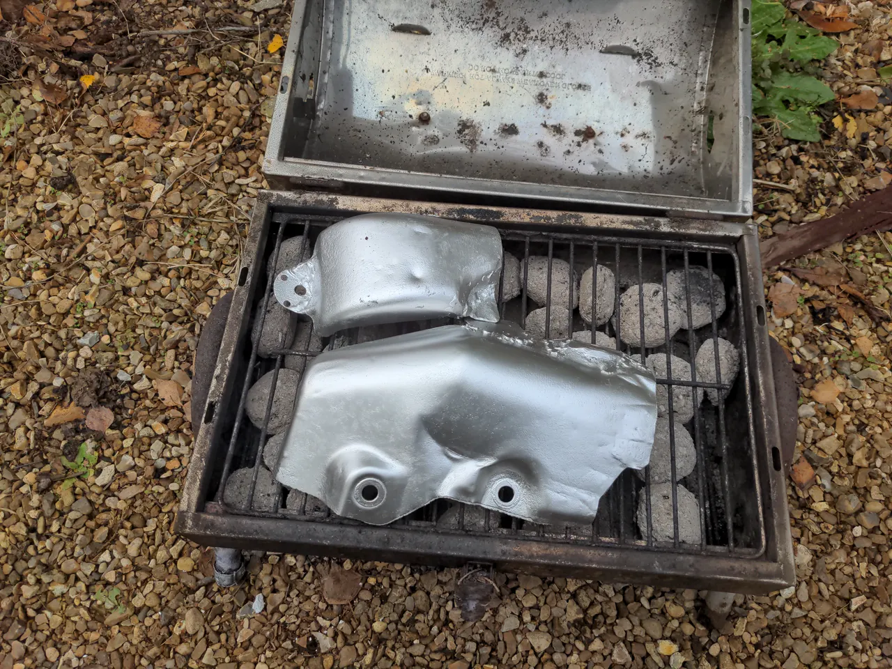
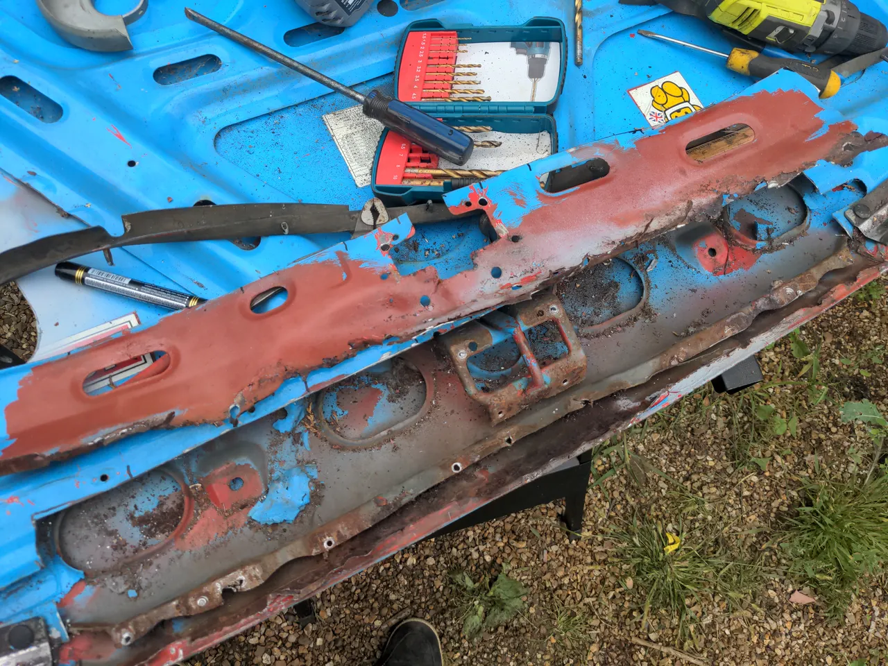
I originally planned to fold this into the upcoming "turbo" part of the rationalisation series, but there are parts of that which are still not complete, and are entirely out of my hands at the moment. Also, the heat shield turned into a multi-weekend mini-project in which I learned some things, so maybe you can too.
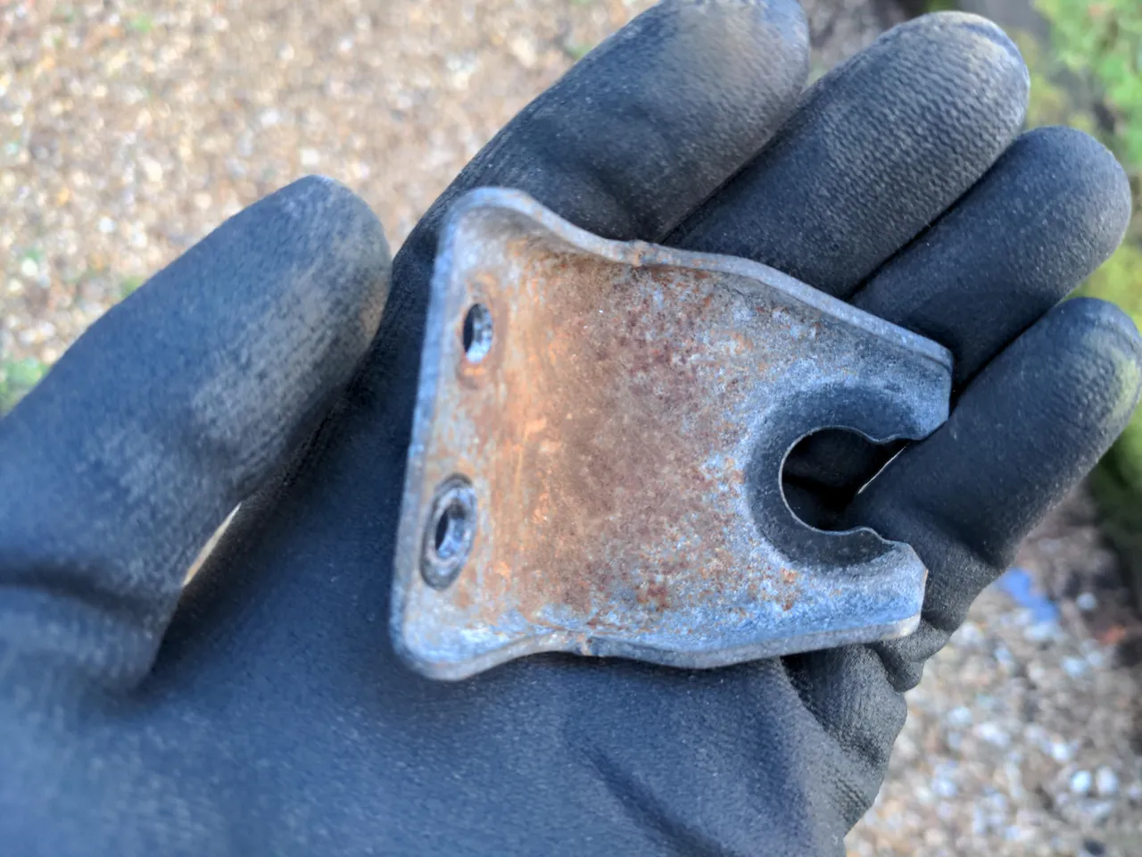
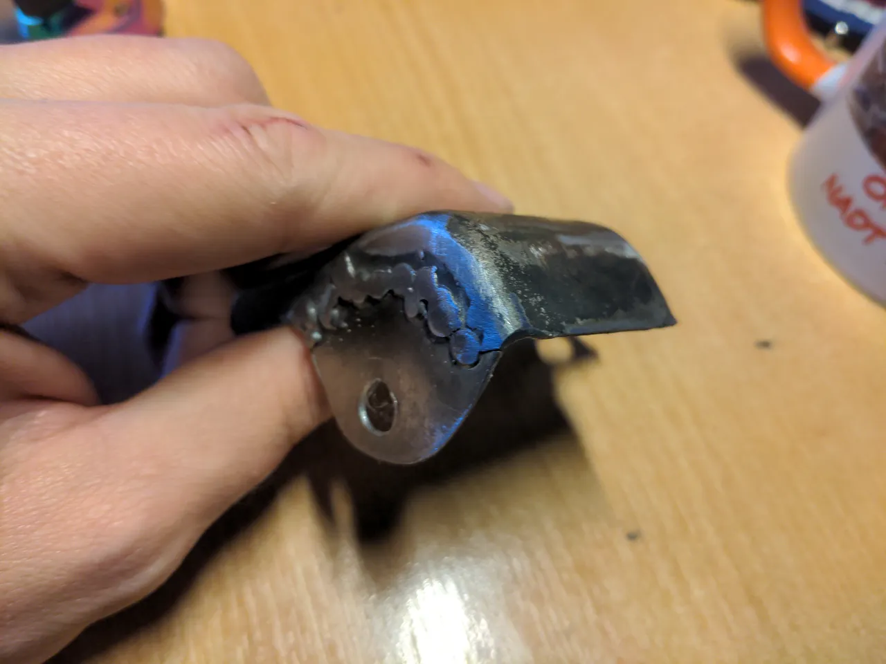
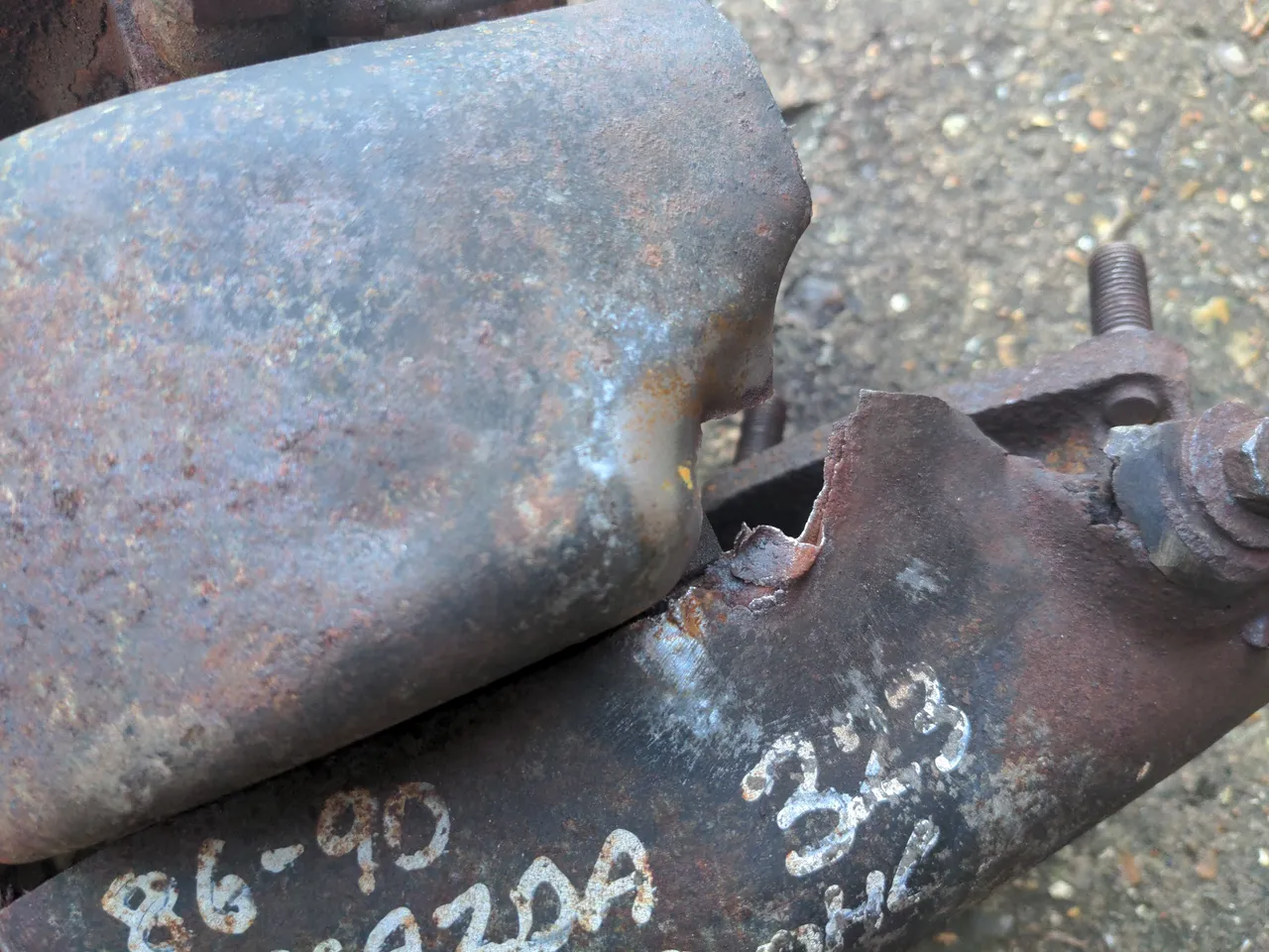
Actually, it's my heat shield bolted to a scabby, worn-out, nearly-four-decades-old turbo. The heat shield is made of two sections. In the photo above, it's the piece of metal with white scribbles on it, and the piece of metal bolted to that. It is supposed to protect things in your engine bay from the turbo's extremely hot turbine housing.
Mine was not in very good shape. It had started to rot, and when I unbolted it with the impact wrench, a bolt came undone, with a chunk of both sections of the heat shield attached to it.
As I had other things to do, and no clear plan for what to do with my turbo (if I had proceeded with a completely different turbo I wouldn't be able to re-use any part of the heat shield), I filed it under "I'll deal with that later", and stopped thinking about it for several months.
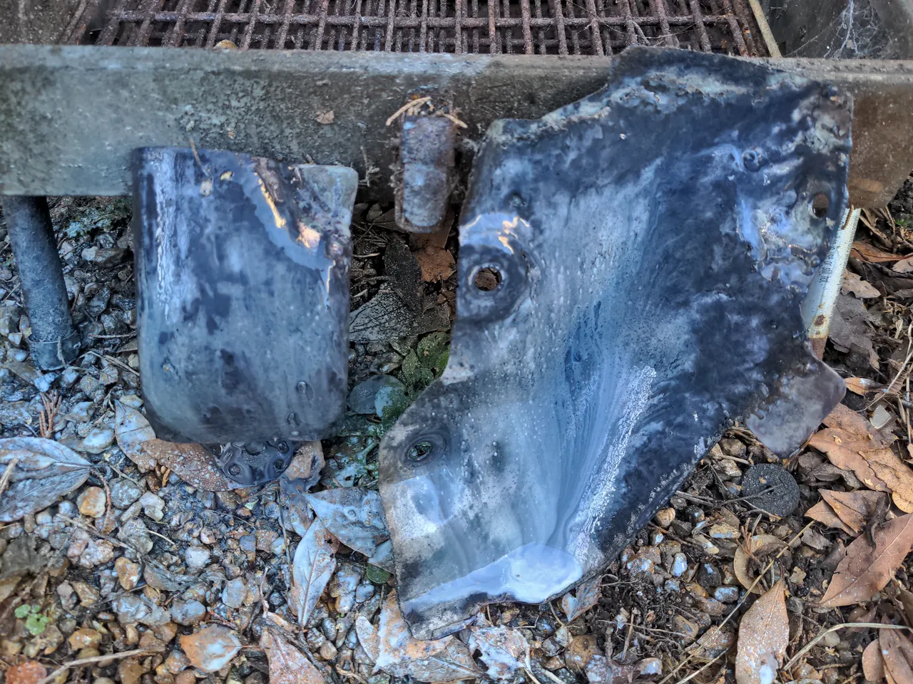
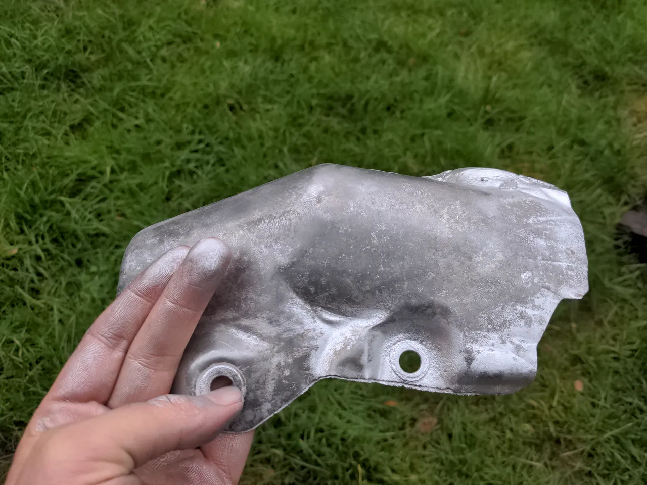
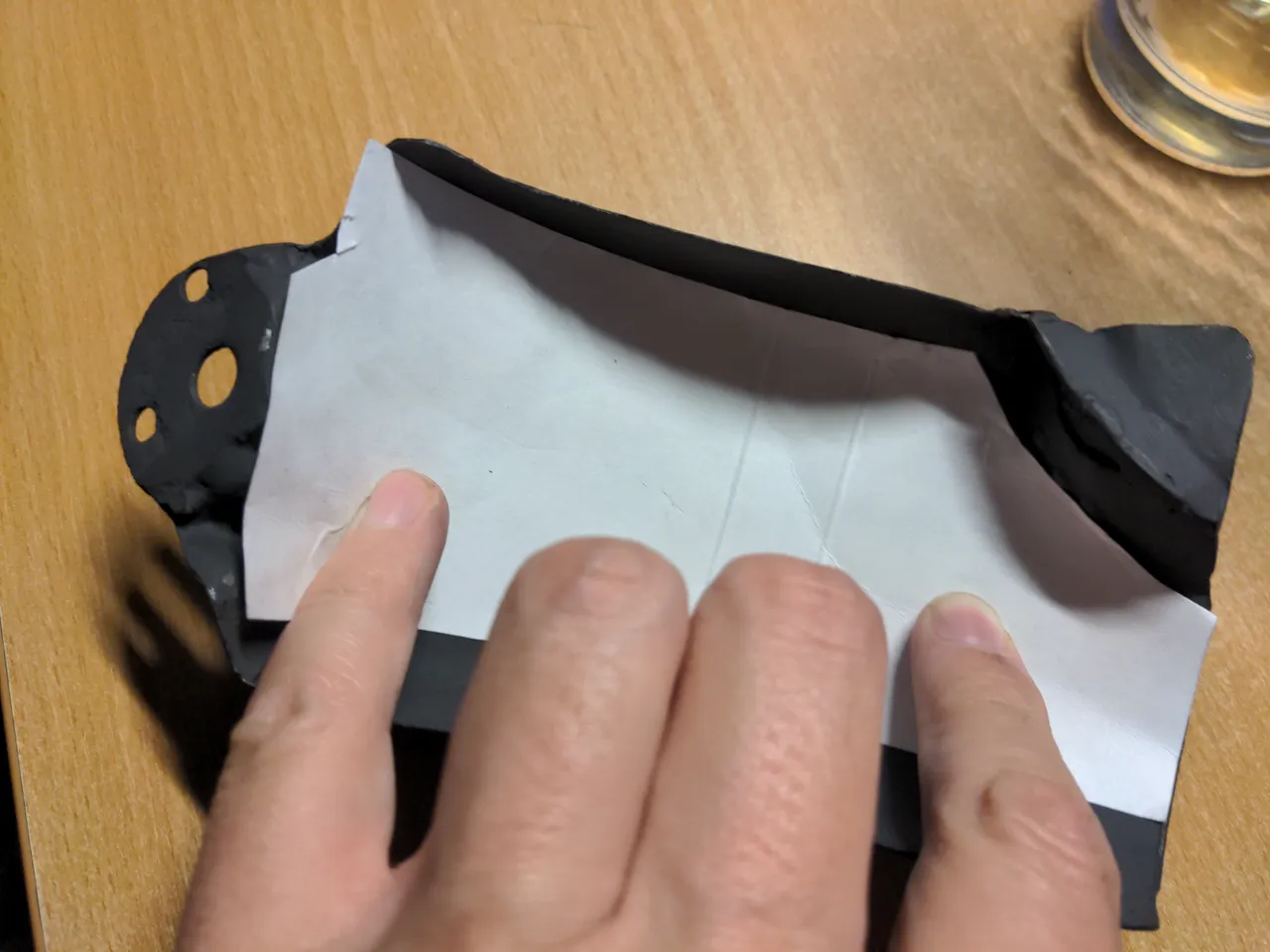
When I returned to the heat shield, I planned to make a new one, because I thought the larger section of the heat shield would be impossible to repair. It is not a solid sheet of metal; it is a sandwich made of two sheets of 0.4mm-thick steel - far too thin for me to weld. In between those sheets is a fibrous heat-resistant material. Because I have probably inhaled quite a bit of it I shall pretend that material is fibreglass, and is definitely not some other fibrous material that was rather too popular for its heat-resistant properties in decades gone by.
I did not enjoy the idea of making a new heat shield, because the correct material for making heat shields is about £150 for a 30x25cm sheet - and the chances that I'd get it right the first time weren't very high, so I could count on buying a couple of sheets. That would be a rather small expense in the unending stream of expenses that the 323 GTX has given me; one sheet costs a little less than one-sixth of a turbo, or one-twenty-secondth of an engine rebuild. On a whim, though, I figured that I may as well try to fix it despite being sure I would not be able to; I wouldn't have really lost anything by trying other than some offcuts of steel, some consumables, and a little time. So I made a very loose plan for some repair sections out of some cardboard...
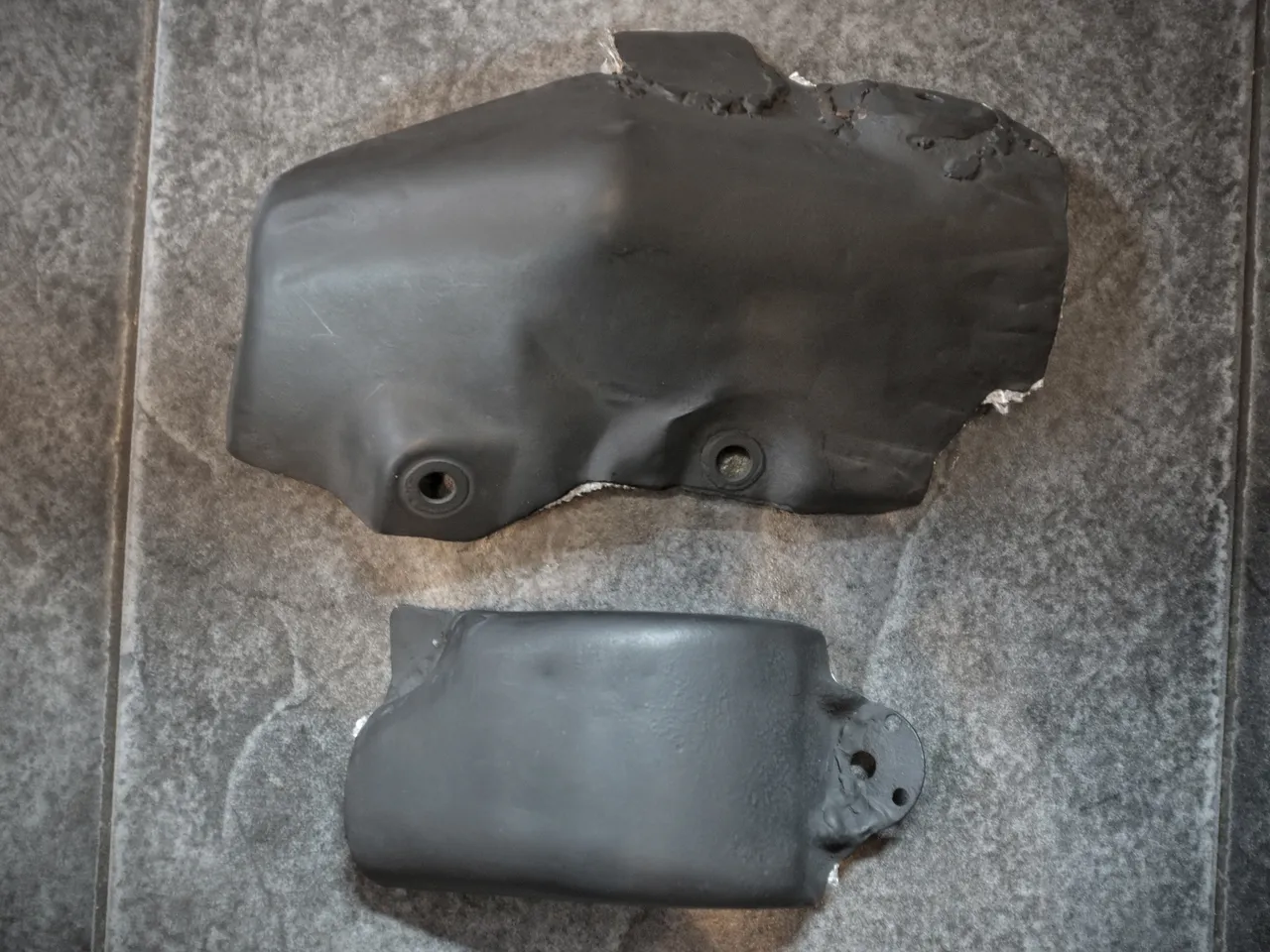
It worked! That is the kind of welding that would fill a YouTube comments section with horror, and I'm OK with that. The excuse is that the metal was paper-thin and that I'm using a worn-out 20-year-old MIG welder which doesn't work at any wire feed speed other than "full send". The full truth is the previous sentence plus the fact I do not weld often enough to be good at it. Still, it's out of sight so it doesn't matter how ugly it is, and these crude welds are strong enough for these non-structural purposes. I went back over some of the areas the next weekend because I wasn't happy with it; it didn't look much better than this after the second round.
Anyway, that was a small success; I did a minor modification with an angle grinder to accommodate the new CHRA, de-rusted the rest of the heat shield with Jenolite rust eater...
Which always makes it look worse while it is working...
...and I could have left it there. Having an unpainted steel heat shield was better than what I had, which was a disintegrating unpainted heat shield. But I wanted to paint it. That would mostly be to make it look nice, but that would also give it a better chance of lasting another 36 years.
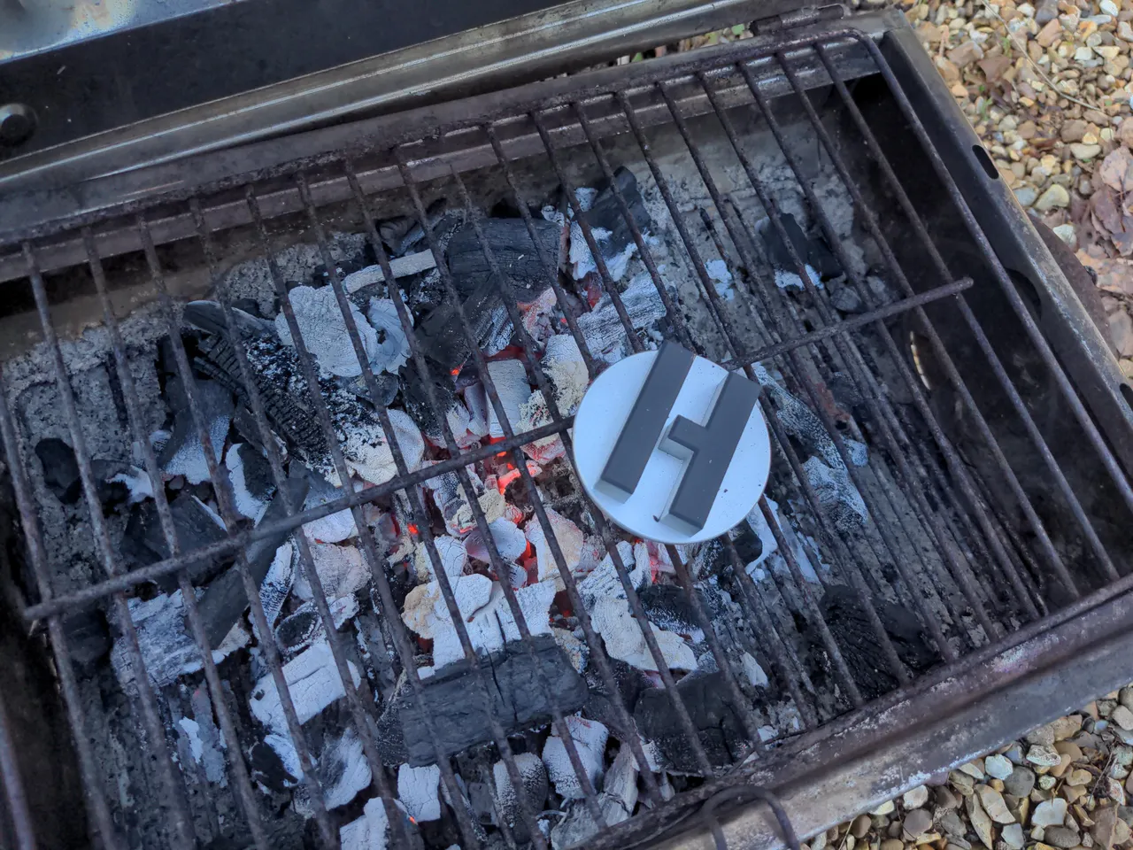
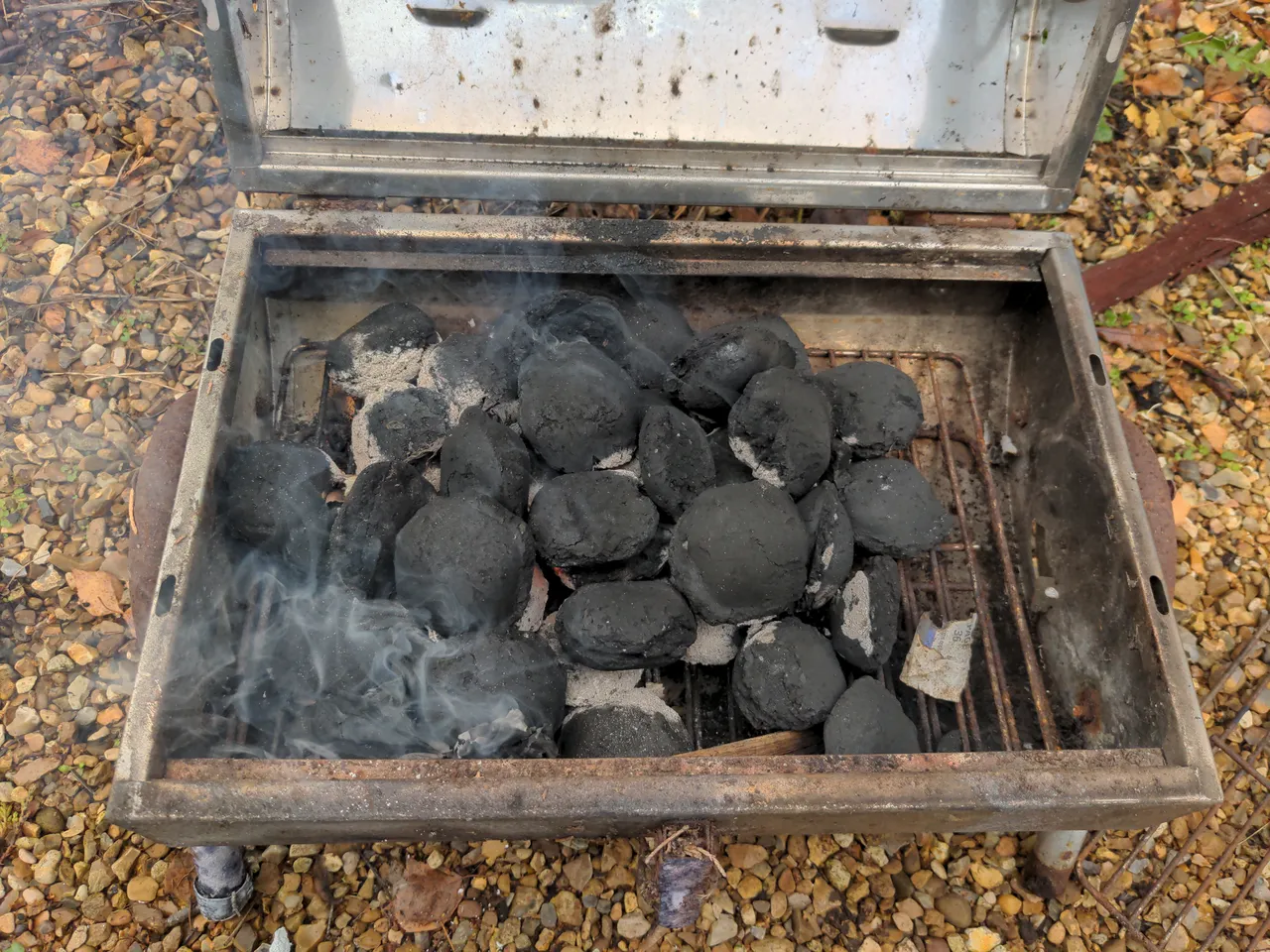
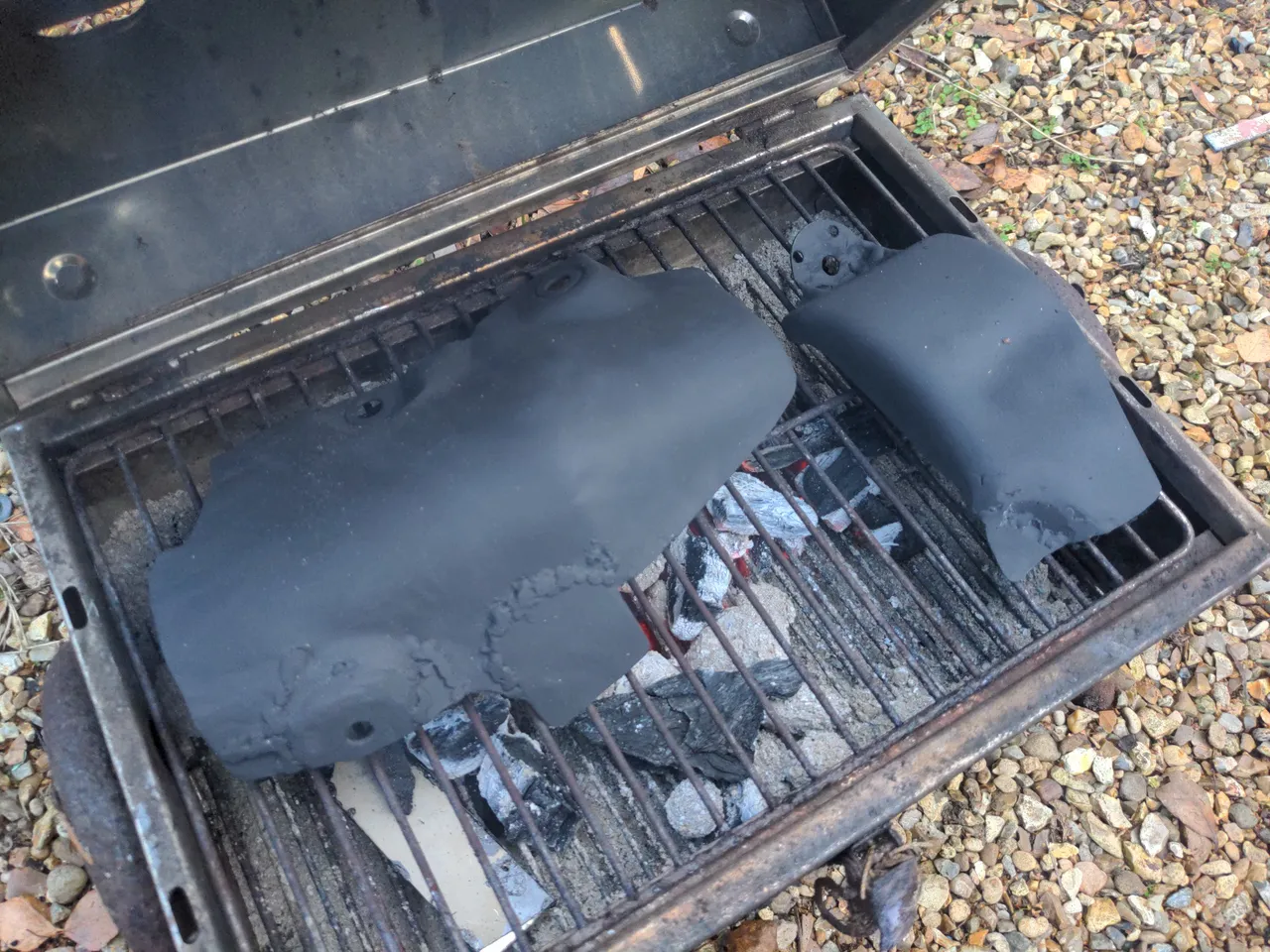
The temperatures near the turbine area of a turbocharger can be quite extreme, hence the need for a heat shield. For paint to survive in this area for any time, it needs to be special high-temperature paint, and all paints of this type require curing in a hot environment, usually in the region of 150°C (300°F). I previously attempted this by improvising a solar oven, but with no sunshine to be seen in England for the next six months I decided to liberate an old BBQ and use that for generating a lot of heat.
Totally normal people, doing totally normal things.
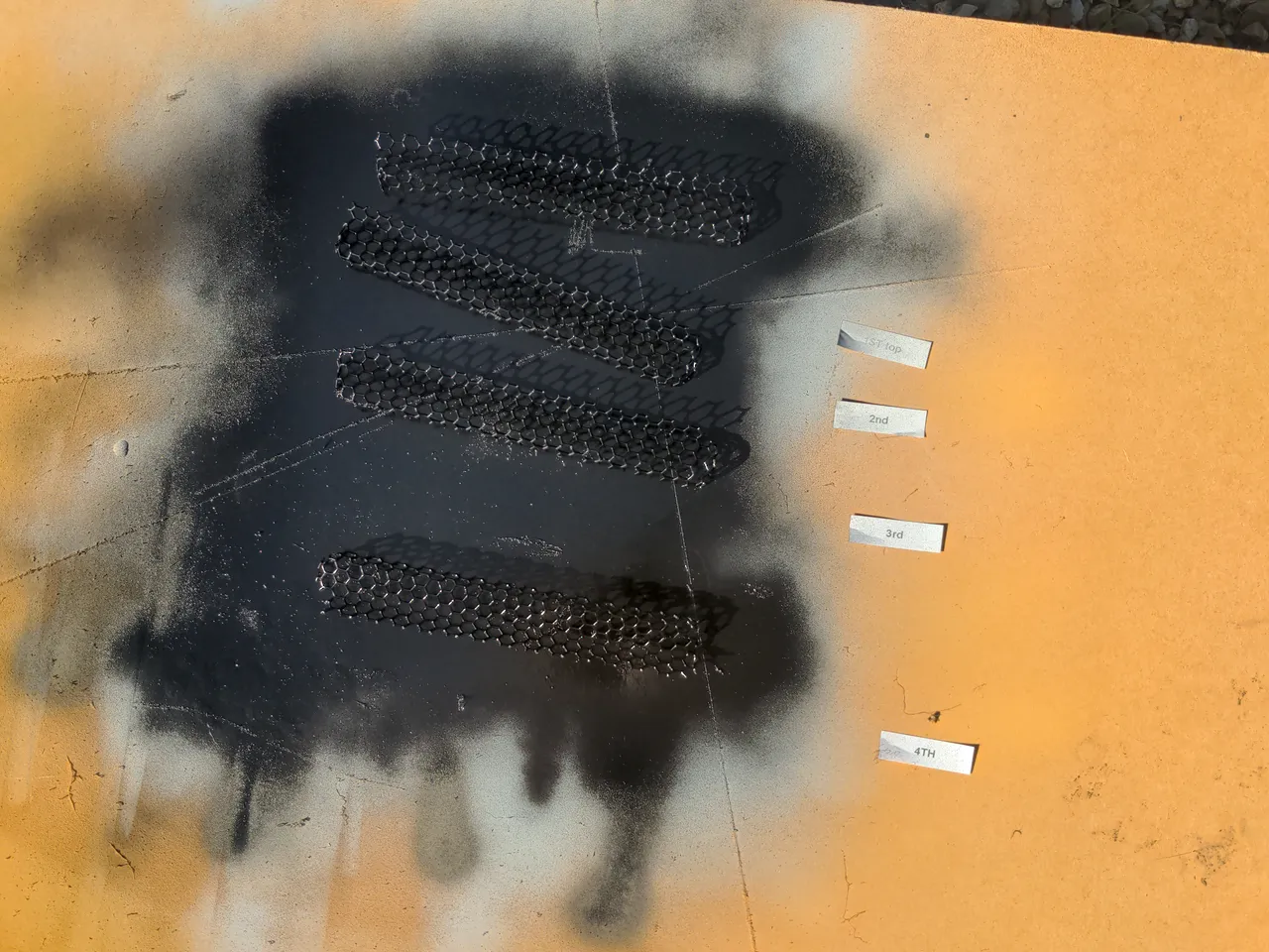
I tried to time all this so as soon as the BBQ was uncomfortably hot, the heat shield would be painted and ready to go in the "oven". Some time later, after curing and cooling, the result...
...was a total failure. The paint came off in my hands while handling it, as if I had thrown flour onto the part and expected it to stick. I don't know why this did not work. The surface was impeccably clean when I sprayed it, it was sprayed under relatively-controlled conditions, and the BBQ was definitely hot enough to cure the paint. Maybe the lesson here is not to buy no-brand-in-particular VHT paint. That probably means I need to revisit some earlier stuff since I have pipework painted with the same silver VHT paint.
Anyway, I wiped off what was left of the VHT paint and tried something else! Something I already had, which was this stuff:
It is Jenolite black BBQ paint. It is good for 650°C. That is as hot as I'd ever want it to be at the heat shield; if it got much hotter than that I'd have some other problem like the car being on fire (though later I will mitigate that too). It is less blingy than the silver VHT, but that is probably better, because it won't look like garbage once it inevitably gets dirty.
The instructions on the can say nothing about using heat to cure, but product descriptions online seem to hint at it. And, if it's going to burn off to some extent on its first heating I would rather that happen in controlled conditions, like on my BBQ, rather than on my car, where it would probably result in a scramble to work out what was causing all the smoke.
After cooling, nothing came off in my hands, and after spraying with electrical contact cleaner and wiping it more thoroughly only a small amount of black came off. That is as obviously attributable to the soot from the BBQ as it was from the paint, so I called that a win.
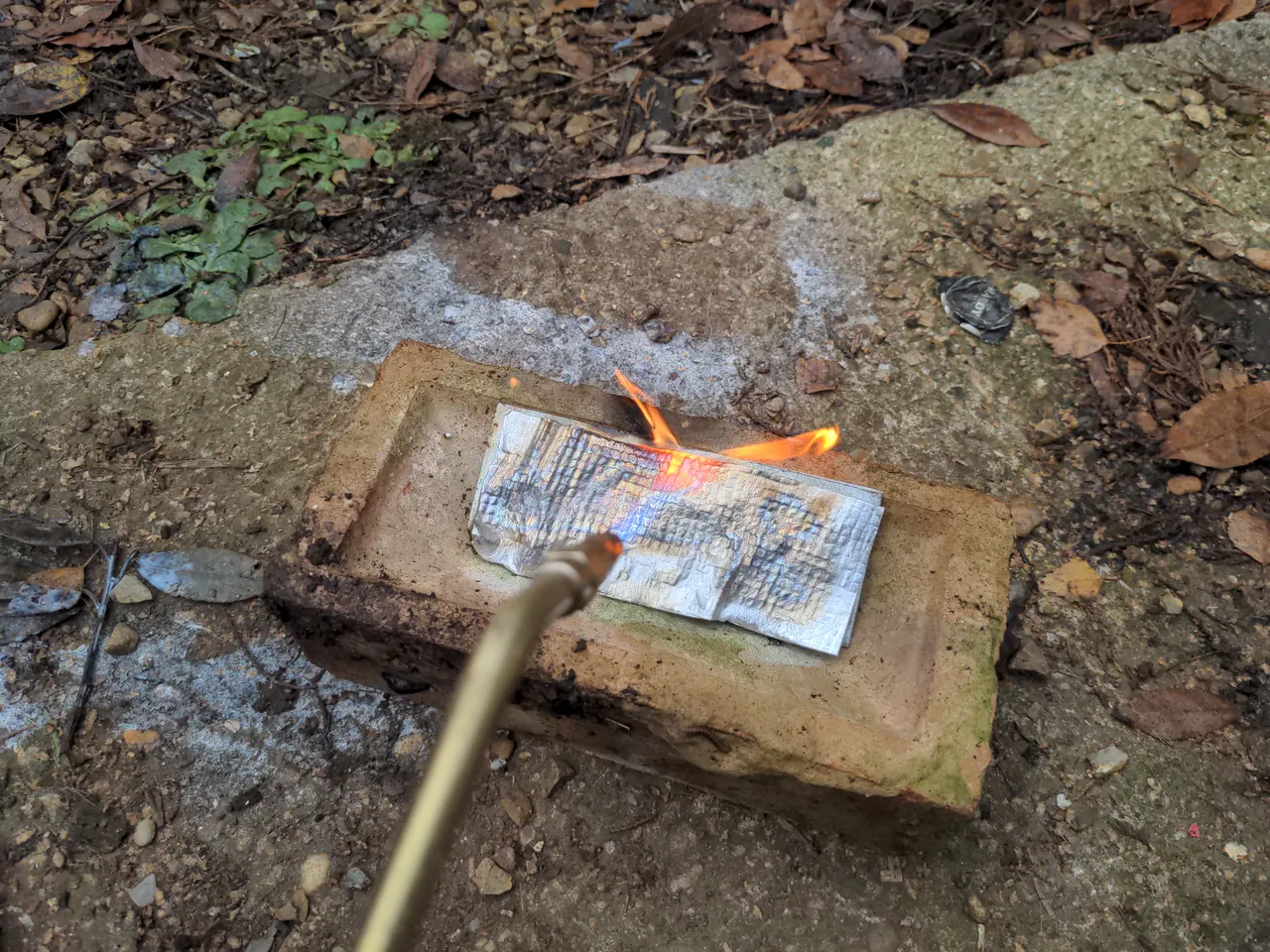
And, I could have left it there! But the black paint is just cosmetic. Inspired by this post, I decided to give the heat shield some heat barrier properties as well. I experimented with a couple of self-adhesive materials here. I believe their rated temperature ranges; I wanted to know what their failure modes were when I exceed those temperatures. If I have a thermal problem down there I do not want anything to combust.
That is why I spent some time on a quiet Sunday afternoon setting things on fire with an oxypropane torch.
An oxypropane torch burns at about 2000°C (3600°F). That is about the same temperature that a UFO must endure while entering Earth's atmosphere; i.e. far beyond anything I am likely to see at my turbine housing, and far beyond anything these heat barrier materials are designed to withstand. I subjected it to these temperatures for two reasons. One, because it is very fun. Two, because extreme beyond-design-basis temperatures will illustrate the failure mode of the material.
The heat barrier pictured above caught fire at these temperatures. I'm not naming the material because I don't want to "name and shame" when I am subjecting it to temperatures far beyond anything it is designed for. This material may well yet be useful in future; I tested this material inside my BBQ as well while curing paint and it held up very well. I may well use the remainder of it to modify my BBQ to retain even more heat for future paint-curing exercises, and if it surprises you to read the words "modify my BBQ" here you might not know me very well.
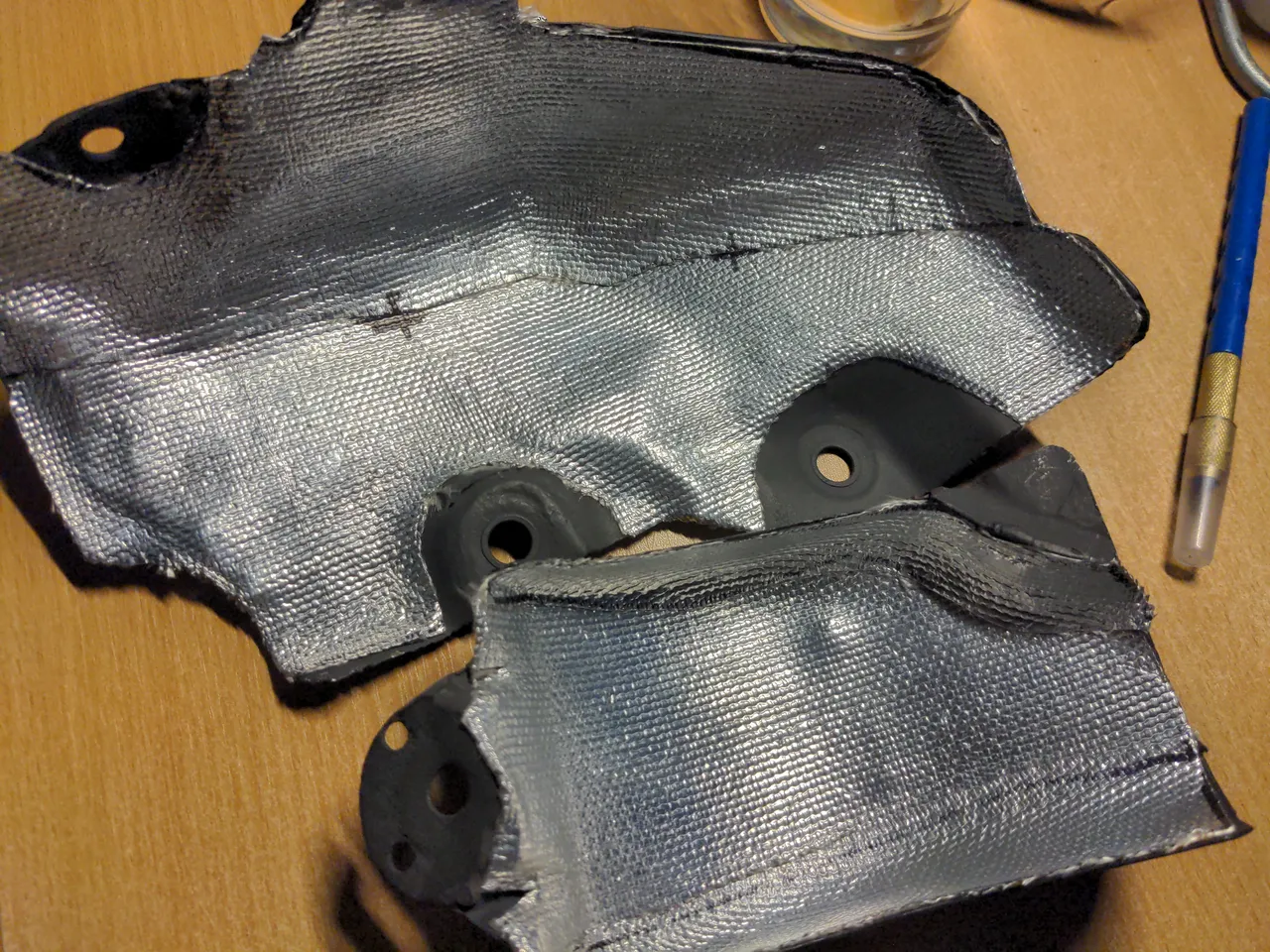
The winner was Thermo-Tec Aluminized Heat Barrier (which was also used in the post linked above). It is self-adhesive, bonded to fibreglass (violating a promise to myself to never work with fibreglass again; I was itching for days), bonded to a thin aluminised layer. It is rated to 1093°C (2000°F), which is somewhat hotter than the worst-case scenario temperatures near my turbine housing. More interesting (and more fun) than any of that, when it failed at the oxy-propane torch the adhesive and the fibreglass substrate hardened (rather than caught on fire) and the aluminised coating fell off. That is a graceful failure.
I found it easier to apply the heat barrier in multiple sections. The smaller part of my heat shield required three, the larger part needed two. It's fine for the sections to overlap at the edges; you are not sufficiently space-constrained for a tiny bit of extra thickness in places to be an issue, and a little overlap is better than leaving a small gap. I also found it very useful to make cardboard templates first; it has about the same flexibility as the heat shield material, but rather less awkward to work with, and it's free to make mistakes. Thermo-Tec very thoughtfully included some cardboard for this purpose, with their packaging.
And if you're wondering, yes I made the obvious mistake when tracing around the cardboard out the material the first time. I won't tell you what that is; you will make the same mistake exactly once, and you won't feel bad about it because you know I did it too.
And with all that done, it looks pretty sweet, bad welding notwithstanding.
As always, with the car some distance away undergoing an engine rebuild I am doing all of this blind. I won't know it'll work until I run the car up to temperature for a sustained period of time, which is some time away. I must trust that the paint and the heat barrier are going to work at their rated temperatures, that my turbo isn't going to run vastly hotter than any turbo normally does. Other than a single hole to drill where the two sections overlap (which I cannot do until the exhaust manifold is back to allow me to bolt everything together, and its current absence is yet another story for later), I shall call that finished.
I had an overheating episode in 2020. It was not fun. It lacked so much fun that as part of the 323 GTX rationalisation subproject I wanted to give the 323 GTX some bonnet vents. Actually, I don't think bonnet vents would have saved me in that situation, because it dramatically overheated at low speed, but still, that scared me into doing as much as I could to keep it cool in every situation.
Putting vents into a bonnet requires making holes in the bonnet. Fortunately, I had a spare bonnet for this car. Actually, it's the original bonnet for the car; the reason for my original bonnet being off the car is too long to go into here. The one currently fitted to the car was fucked by an idiot, and that is also something I won't go into here, so the original bonnet was intended to go back on at some point.
Anyway, I am lucky to have a spare bonnet for this. It is probably the only bonnet in the country which is not fitted to a car.
It might seem like a strange act of sacrilege to make holes in it, like sticking a sunroof on an E-type but more so. Oh well; originality went out the window a long time ago, and it's not like there's any other owners around to criticise me anyway! :D
So, vents. You're spoilt for choice these days, as old people are obliged to say. Given my insatiable urge to over-solve every problem, I decided to set myself some arbitrary criteria. Otherwise I would just be able to buy whatever vents, make a hole in the bonnet, and glue them in. That would be too easy!
Of course, I wanted something functional; that requires a rear-facing vent and not a scoop. But also, I wanted something that did not look out of place on a 1980s car. The generic vents that you can buy on eBay for a few quid function as well as anything does. But they are all designed for modern cars; often they are copies of vents fitted from the factory to modern cars. They would look strange on the boxy little 323. I also wanted subtle. The 323 GTX is a very subtle car. There are very few giveaways on the exterior that it is a mental turbocharged rally car at heart and not Grandad's shopping hatch, and I wanted to keep it that way.
Instead of subtle, I ended up impulse-purchasing a pair of Ford Sierra RS500 Cosworth vents instead! Woohoo!
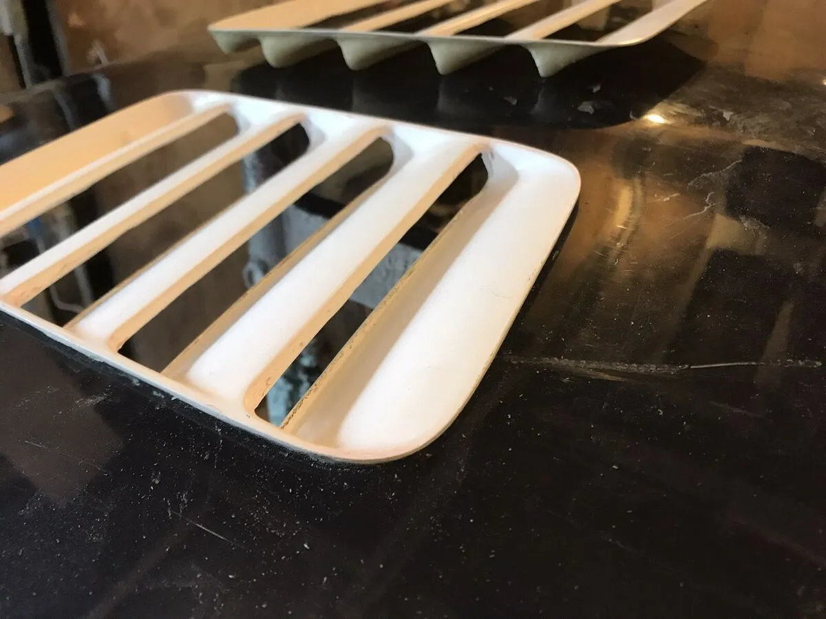
Don't worry, these are not genuine RS500 vents! Because I am not insane. There were a couple of genuine ones on eBay with a £300 starting bid. I didn't really want to pay that for something I was not sure would actually work, nor did I want to deprive someone's RS500 or Sierra Cosworth project of its proper vents. My vents are fibreglass copies from this seller on eBay that cost about £65 shipped. Mine have a lip on them to allow them to be fitted easily to not-RS500 bonnets like mine; otherwise, they are very close to the originals.
I liked them. They would not look completely wrong on the 323 GTX, because both the GTX and the RS500 were race cars at heart, born from homologation necessities in the same era.
Anyway, I ordered them, they showed up a few days later and oh no, they are quite big.
They're so big that it wasn't clear they would actually fit anywhere. This is the sort of thing I should have figured out before buying them, like by finding an RS500 and measuring the vents, or asking the seller, but that's not how I work. If I was better at thinking through the consequences before impulse-purchasing stuff I would not own two project cars.
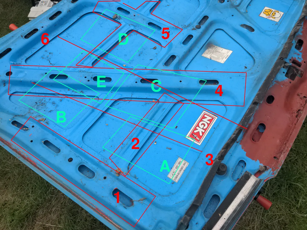
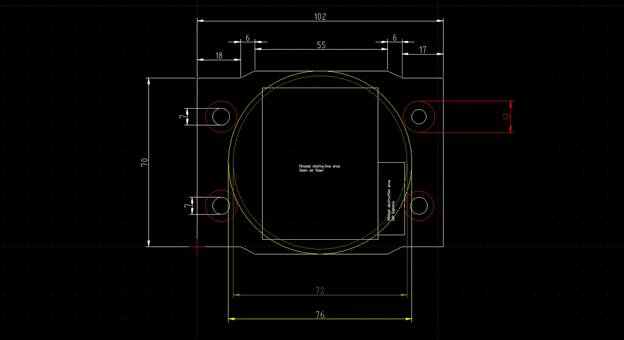
Here's a picture of the inside of the bonnet. Danger zones are annotated in red, potential locations are annotated in green:
Location A was OK, because it only required cutting out the brace at danger zone 2. However, any location for it would require that it would overlap the styling line (small indentation running the length of the bonnet) at 3, which would look weird. Moving it outboard to avoid this line would put it in danger zone 1, and that would be cutting a lot of strength out of the bonnet.
Location B might have been OK, but it had the same problem of either overlapping styling line 3 or going outboard into danger zone 1, and would have meant cutting into danger zone 4, and it would have been a lot of work to translate the strength cut out here somewhere else.
For styling purposes location C might have been fine, but it meant cutting most of the brace in danger zone 4 too. It also overlapped the line of the bonnet bulge at danger zone 6.
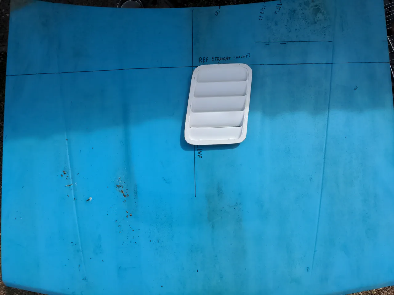
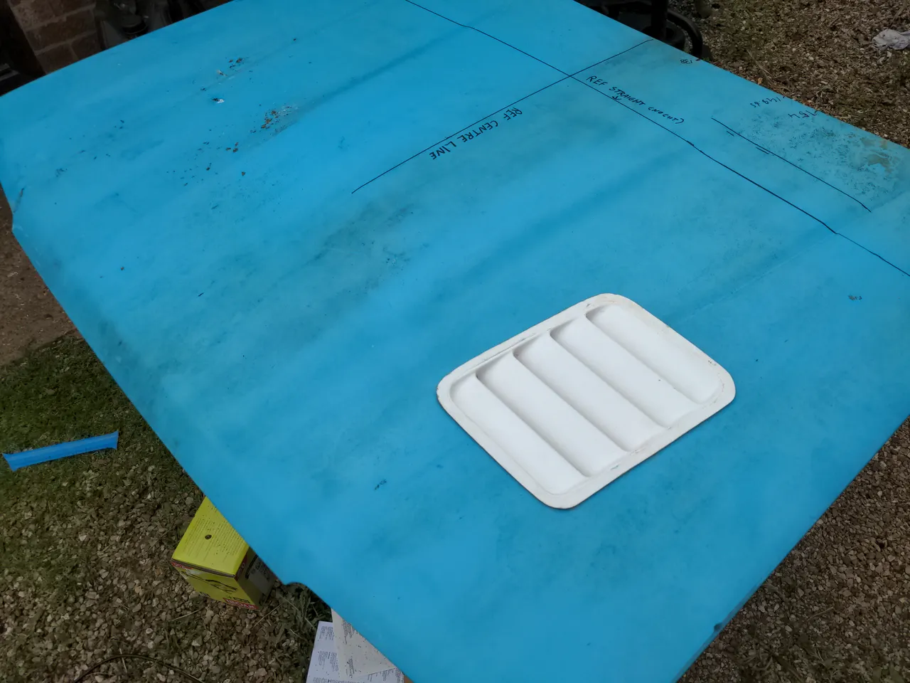
Location D is...a strange one. It would have required cutting out multiple bits of bracing in danger zone 5, but this strength would have been easier to translate elsewhere. I thought it might look a bit weird, so I flipped the bonnet over, plopped the vent on top..
..and decided that yes, this definitely looks weird and I don't like it. It might have worked fine with a vent of some other shape, but this parallelogram shape so close to and overlapping the centre line of the bonnet just doesn't work.
E might have actually been optimal if the bracing was designed differently; it is location C moved far enough back that the bonnet bulge is no longer an issue. But that would have meant cutting the brace in danger zone 4 and the smaller part of 5; again, this strength would be hard to translate elsewhere.
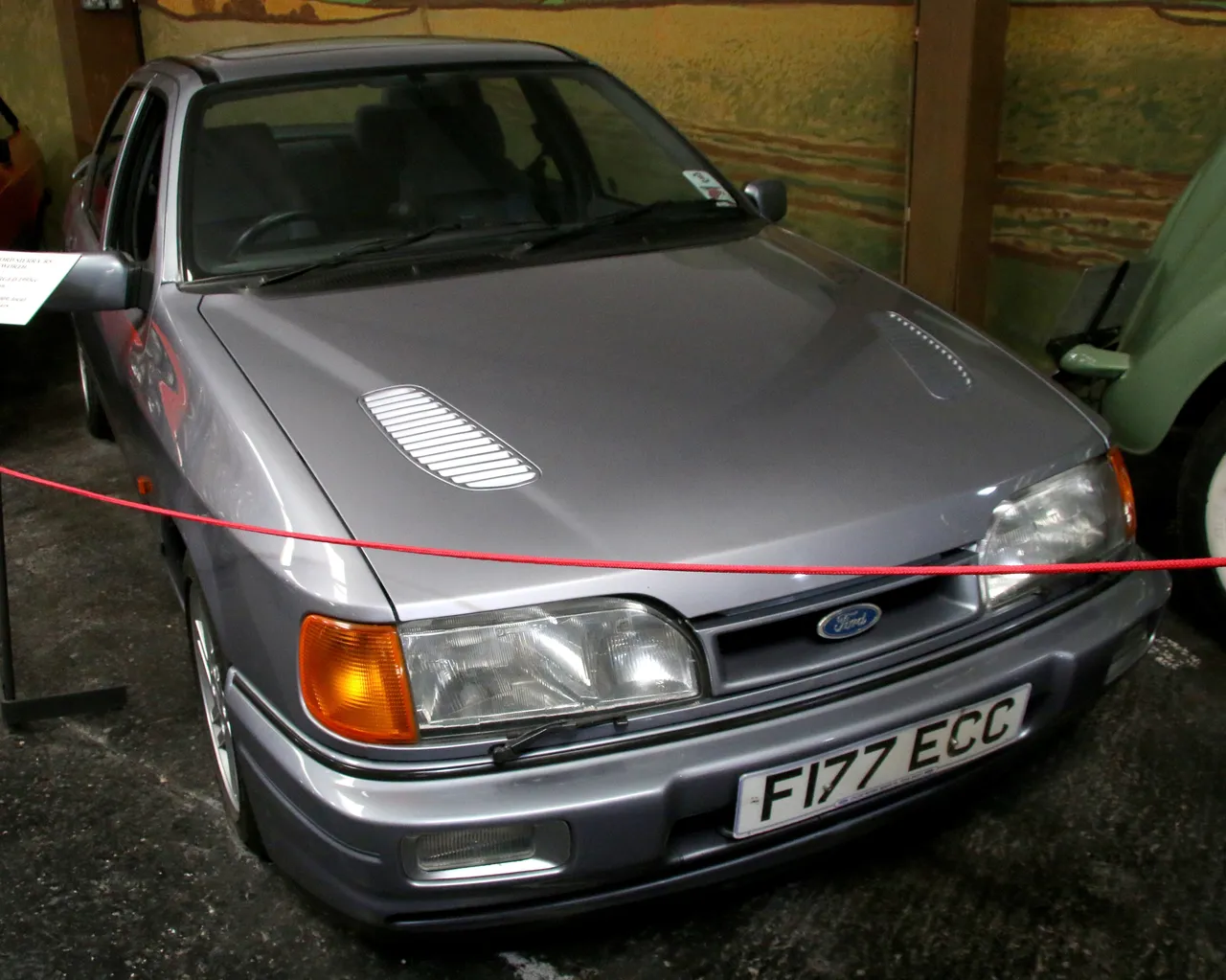
So, after a full day thinking about it, I realised the vent just won't work on this bonnet. At this point anyone else would have just bought a different, smaller vent that'll actually fit. But I'm not the kind to give up, so I decided to look at some photos of cool cars. When doing that, I noticed from this pic of the Sierra Sapphire RS Cosworth...
...that it's actually OK to have a vent being intersected by a styling line. Nobody complained about it on the Sapphire RS Cosworth as far as I know, or even noticed. Thus, location A will probably work fine! Yay!
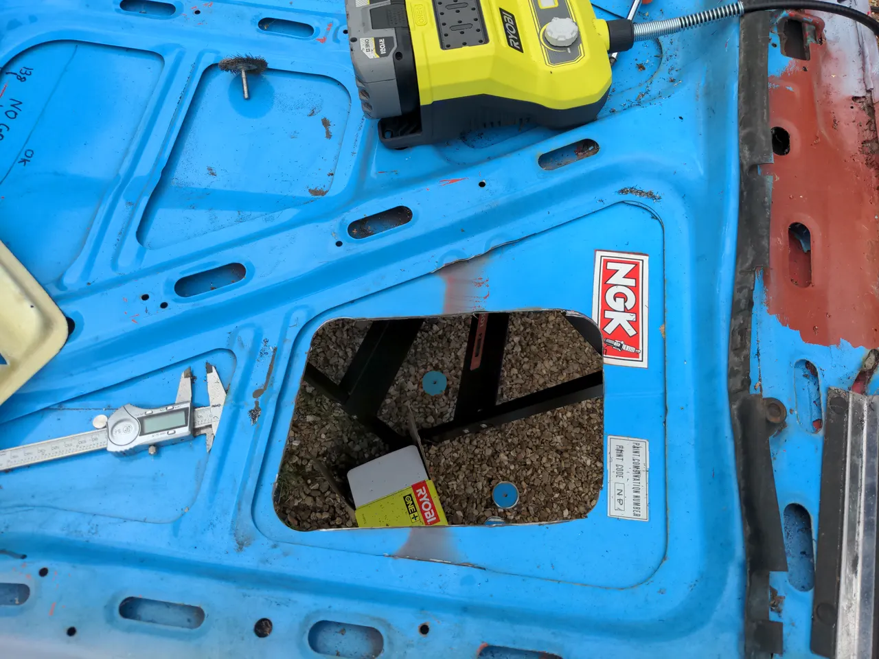
I did a little prayer for courage, cut out some bracing...
As the kids would say these days, sick fam, and innit. That is to say, I liked it, which is just as well, because that hole is never going to be un-made.
Note it is now the vent. My brother came up with the idea of using a single vent, because that would look cool, and also make it look less like it was trying to be an RS500. I agreed - quite enthusiastically, because as well as looking cool this only meant making one big hole in the bonnet rather than two. That would halve the work, and I like putting in less effort if I can get away with it.
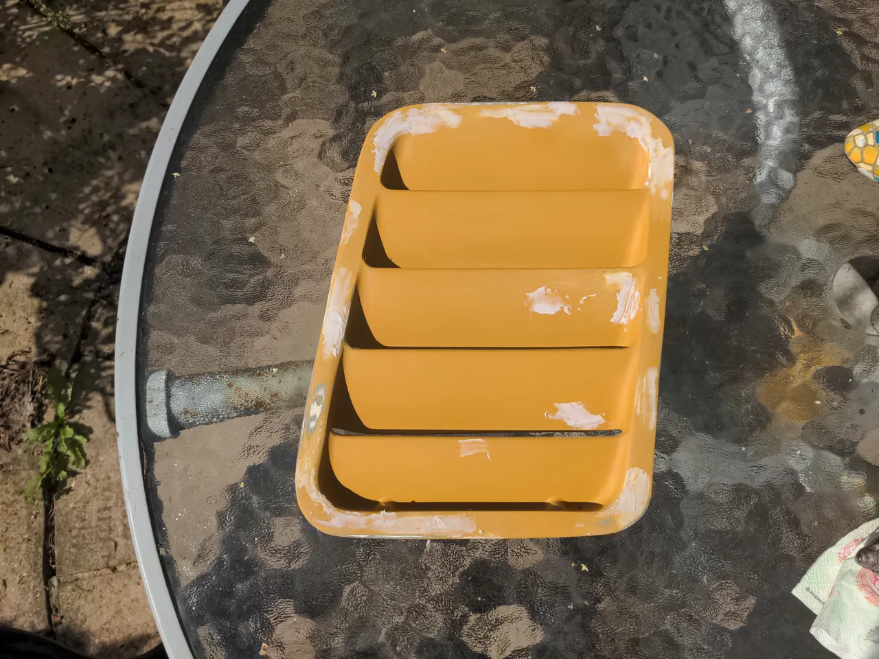
Back to the vents themselves, then. Unlike the ABS vents you can buy for about 30 quid, fibreglass never comes out of a mould perfect. These vents were not perfect, and I did not expect them to be.
I could have left this problem to whoever does the bodywork on my car when it comes back from the engine builder. I did this myself instead.
The process is this:
apply a very thin skim of knifing putty to any low spots
sand them back
apply filler primer
sand back the filler primer
find progressively smaller low spots and go back to the first step
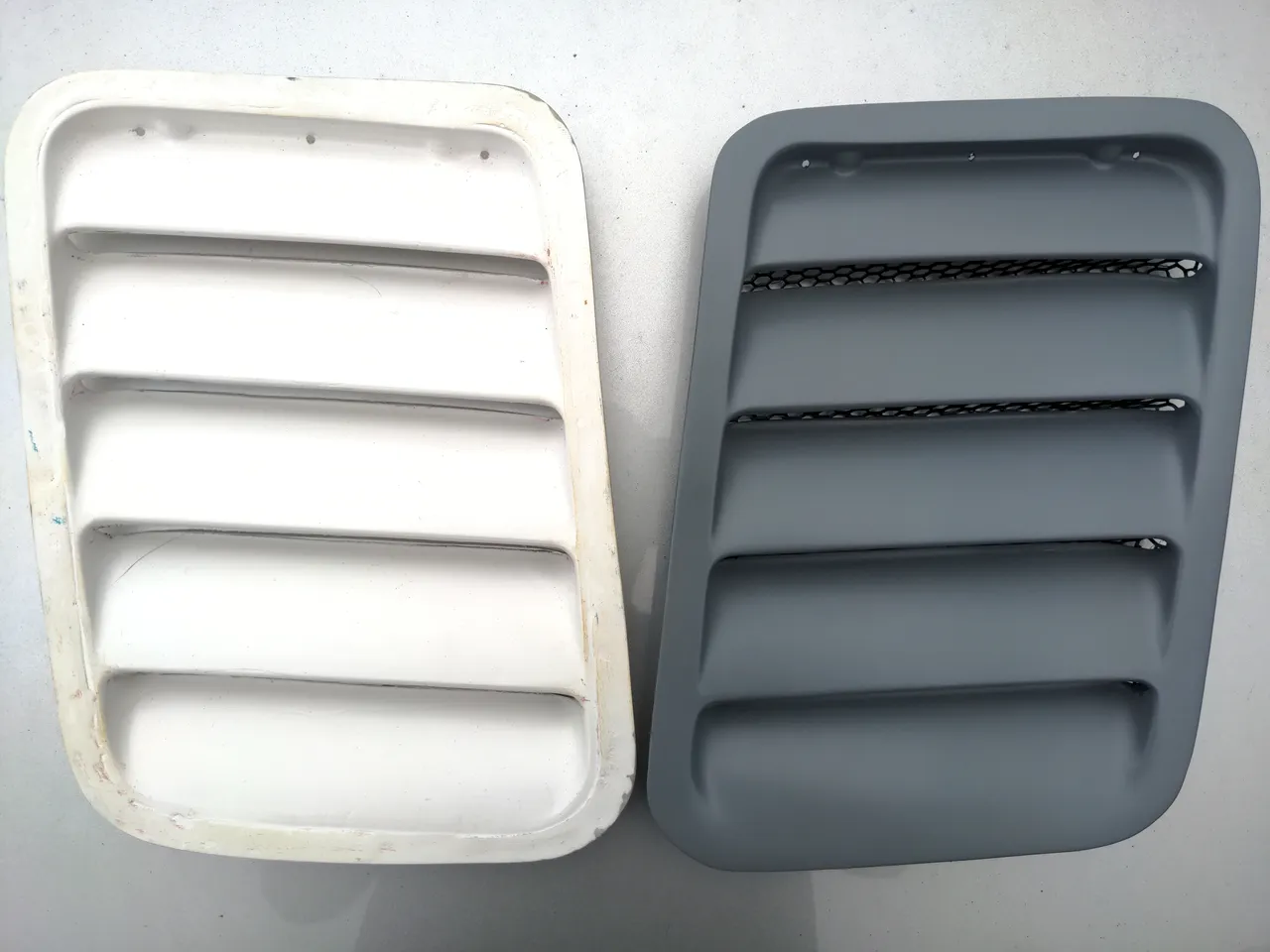
It took forever until I was happy skipping to the last step. Actually it felt like I was making no progress until I put it side-by-side with a fresh-from-the-mould one...
...and realised that at some point I had to stop chasing increasingly small perfections, that I had to consider it good enough, and that I had probably reached that at least one iteration ago. It is Done!
Actually, not done.
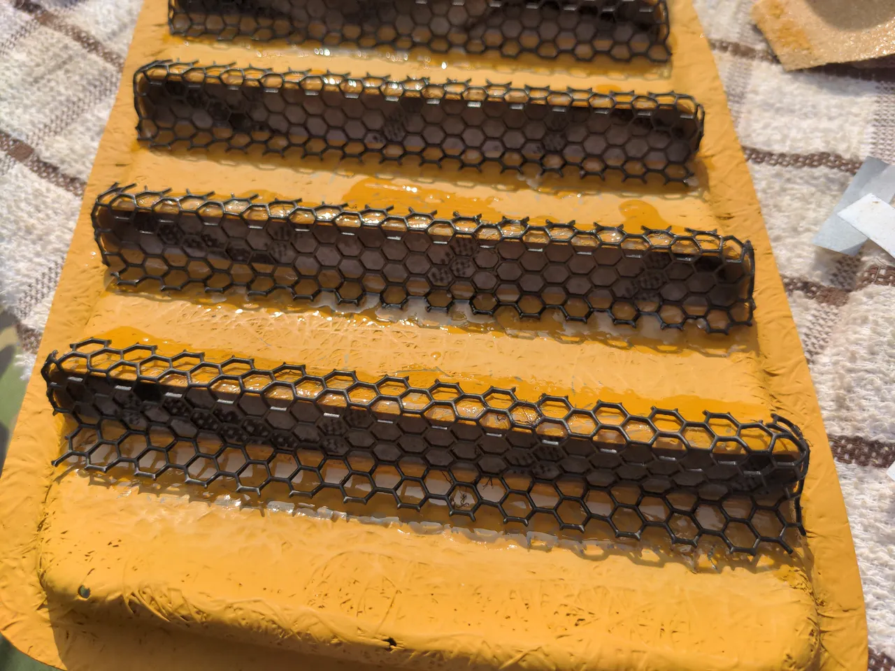
So, my vent will turn one big hole into four, smaller, better-looking holes with rather better aerodynamic qualities. Those four holes allow air out of the engine bay, which is good, but also allow things into the engine bay, which is not desirable. Of course, an engine bay is not a sealed environment; I won't bother to make plugs for the vents to prevent water ingress, because if your engine explodes on water ingress it will do so one day whether you have bonnet vents or not. But, it seemed wise to put something in place to stop ingestion of larger particles, such as sparrows.
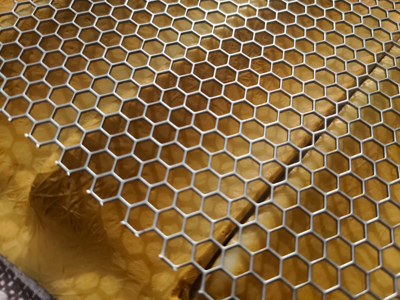
This is steel mesh. It costs about £10 for an A5-sized sheet. I like mild steel because it's easier to work than stainless steel and it survives being bent repeatedly in different directions rather better than aluminium does. The latter is a good characteristic for this application, given that I did not really know what I was doing and might have to un-bend and re-bend the material quite often.
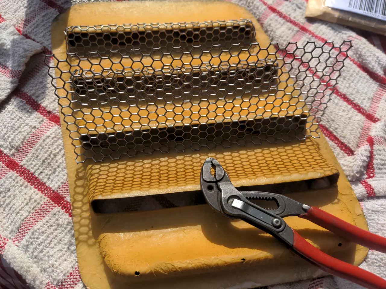
The first one took about two and a half hours, from memory. The others took somewhat less because I almost knew what I was doing at that point.
I painted these immediately after forming them to shape. If it seems like a strange decision to paint them now, bear in mind it may be many months until this vent gets its final coat of paint; I did not want it to gain corrosion in storage. And it is much easier to ensure that it has a thorough coat of paint now than it would be after it was glued in.
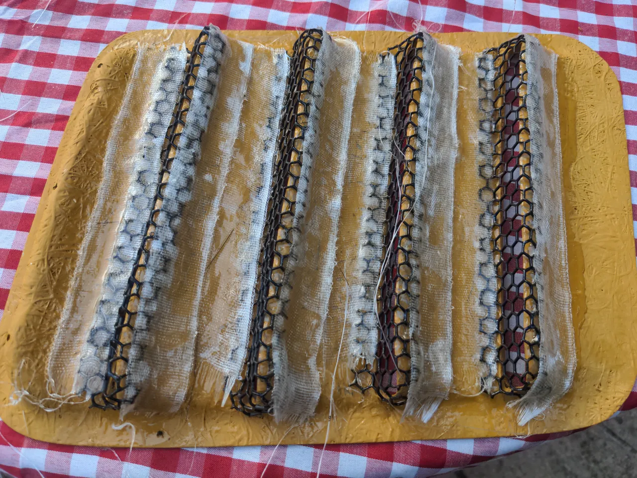
I glued these in with two part epoxy. I learned - maybe re-learned - two things. One is that two-part epoxy is horrifically messy. Another is that I shouldn't be using it on a boiling-hot summer day, because it sets basically instantly. These two things combined are hilarious.
It was a terrible idea. First because epoxy - even far less epoxy than I used - would have sufficed to hold them in place, and it was completely unnecessary. Second, because there wasn't really anything for the strips to grip to (because the mesh has holes, duh), so when it was dry it peeled right off. So this just left me a mess to tidy up afterwards (which took another day). On the upside it reminded me to never work with fibreglass fabric! It itches like buggery.
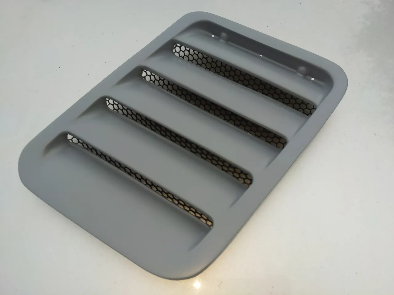
Anyway, with that all done, and the mesh glued in, and a final coat of grey primer...
And that, is making a short story long, and is also how I lost about seven weekends.
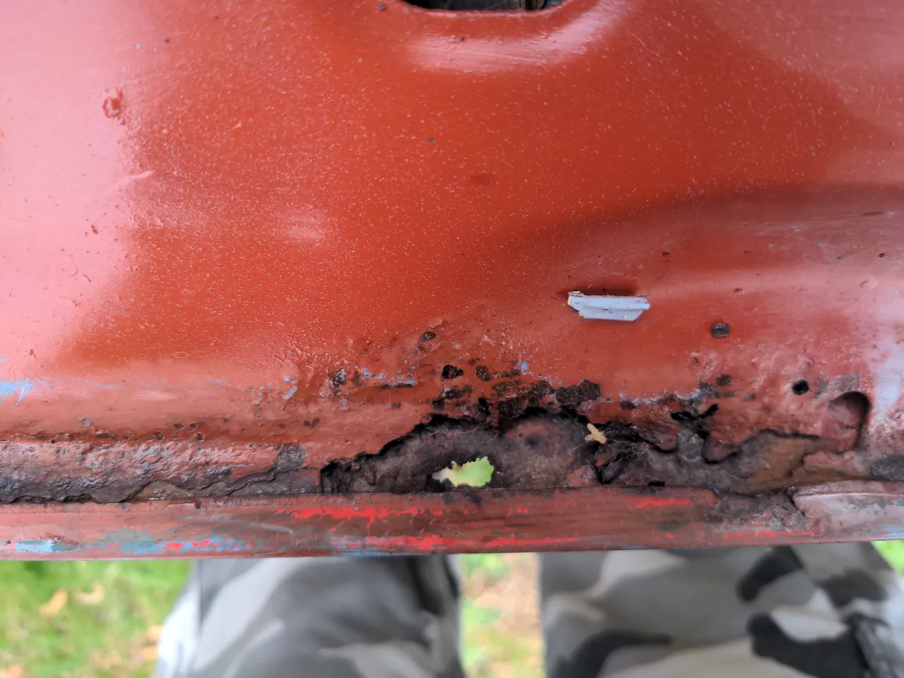
The next part should have been easy. I wanted to get the rest of the bonnet prepped for paint as well. In the earlier pictures the eagle-eyed among you may have noticed an area on the front lip of the bonnet which was coated in red oxide primer. I was aware of this as an area that needed some tidy-ups; the red oxide was applied eons ago to stop rust from progressing. And so I poked around this area with various tools...
...and if this was a YouTube video or my internal monologue, there would be a scream sound effect playing about now. It turned out that much of the front lip of the bonnet was rotten and that the rot had gone all the way through to the outer skin. So as always, things escalated...
...and the rest has become another sub-sub project. As always happens with shit old cars, every job you do generates at least one more job to do. Onwards!
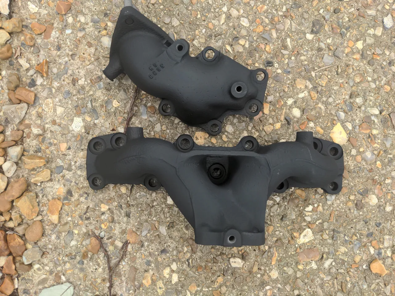
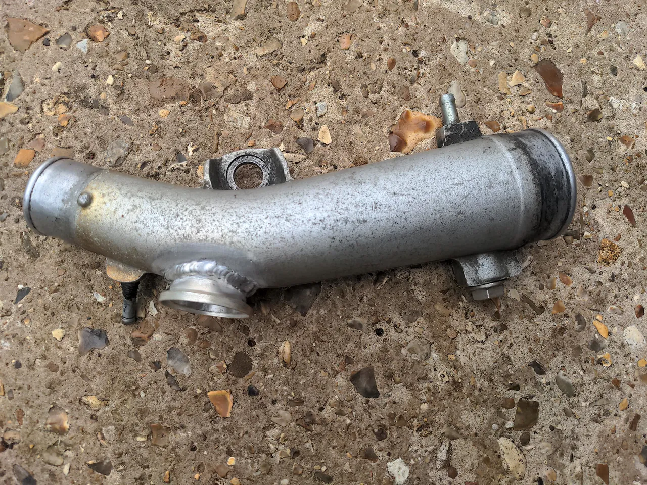
In part 1, I spoke of things being either old or badly modified, and those things being targets of my 323 GTX "rationalisation" subproject. The hard pipe between the intercooler and intake manifold was both of those things, though the bad modifications offended me most. Because I am an idiot (also, because I didn't expect to be writing about any of this in detail), I didn't take a photograph of the pipe before I started work on it. I'm sure you can extrapolate what it looked like from the various pictures (those pictures being rather bad for someone who has a website about cameras because of my phone's pathological desire to focus on the wrong thing). So let's move on!
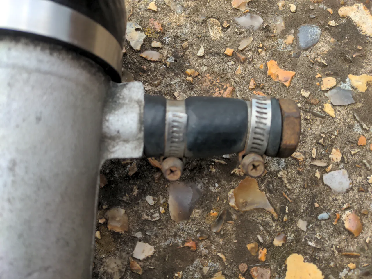
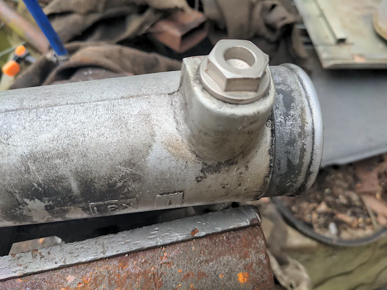
When new, the Mazda had an air-recirculation system to prevent turbo stall when coming off-throttle. This was gone long before I bought the car, and it had been replaced with a dump valve (which vents excess intake pressure to the atmosphere). The vestige of this system was an outlet on the pipe which was blanked off like this:
I don't like this. It works, but it is ugly and unnecessarily space-consuming; it is a bad modification. So, my plan was to remove the hose, grind off the stub of pipe it was clamped to, then do something to blank it off permanently. But it turned out...
...that I didn't need to grind it off, because the stub is pressed in, which rather makes sense if you think about it for a few seconds. Mole grips pulled it out with not too much persuasion. There was no need to apply heat either. That disappointed me because I wanted an excuse to use my oxy-propane torch, because it is dangerous and exciting.
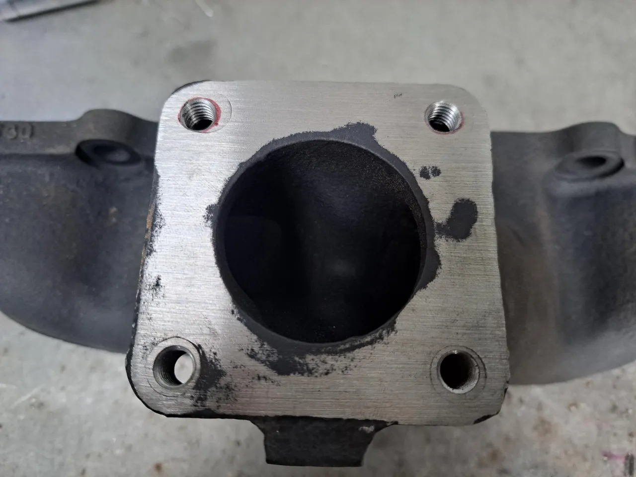
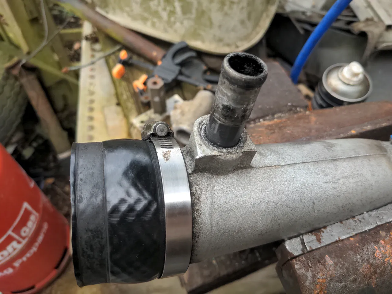
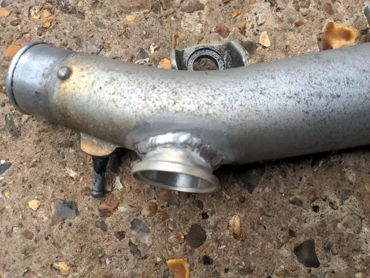
A brief debate with myself ensued as to how to blank off the hole. My first thought was that I could get or make a fractionally-oversized plug of aluminium, heat it up (excuse to use my oxy-propane torch), and force it into the hole with a hydraulic press. My second thought was that if this didn't work as well as I hoped my intake pipe would become a firearm about half a second after the turbo wakes up. That would be pretty sick, actually, but firearms are largely illegal in the United Kingdom. So the third thought was to tap an M18x1.5 thread into it and put a blanking plug (which is really just a somewhat pricey bolt) into it.
That looks tidy, and threading it gave me the option to screw a sensor or something in there in the future.
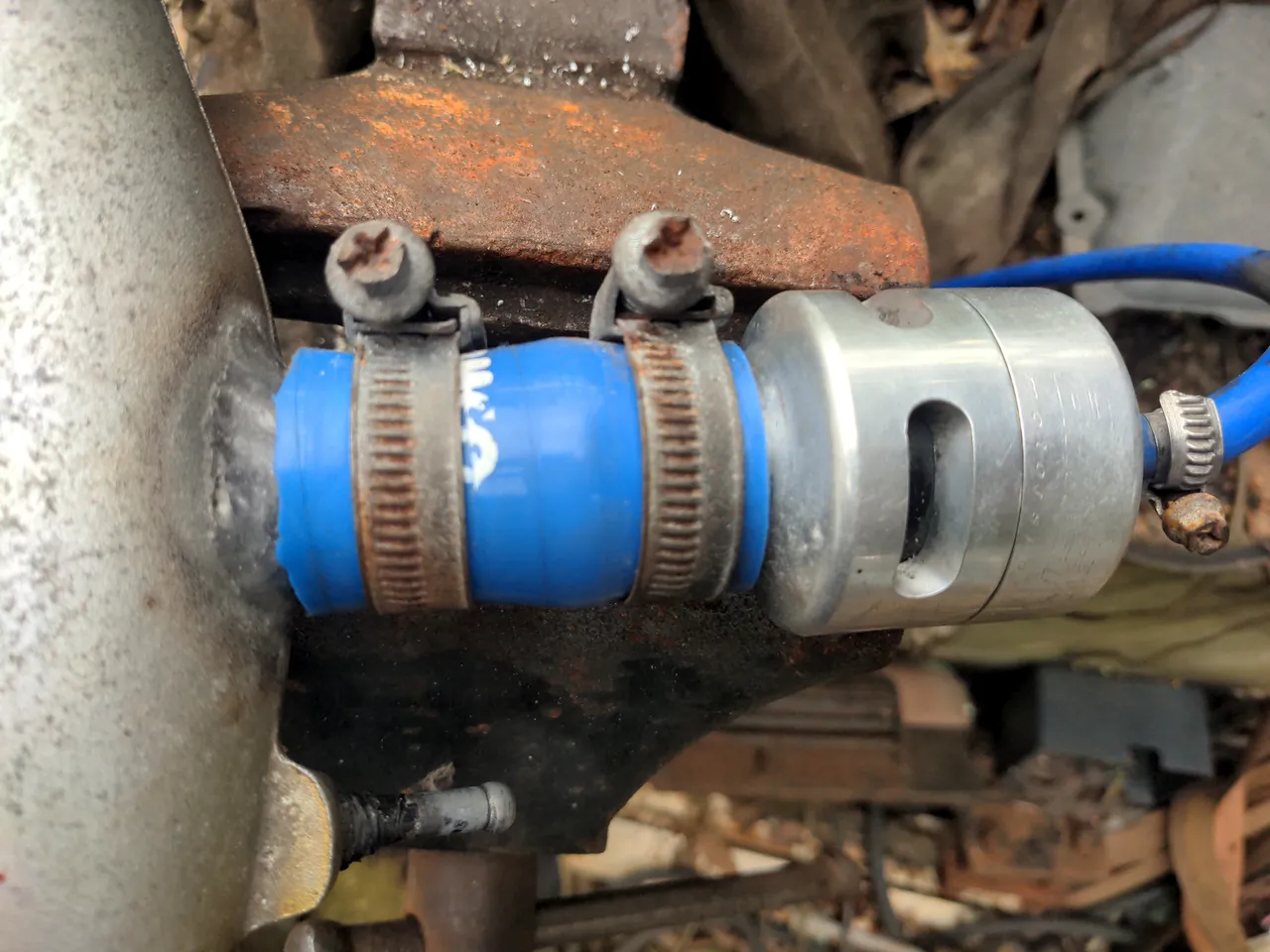
Next up was the dump valve. It is a Bailey DV26 (I think), and it is roughly 20 years old. It did the job well and it sounded nice, but I did not like the way it was attached.
Specifically, I do not like the look of blue hoses; they are too blingy and "modified car"-looking. I actually bought some black hose to replace the blue hose, but changed my mind again because after testing the new hose I still didn't like the way it attached; the use of a coupling hose seemed unnecessarily complicated. I had some thought about cutting a thread onto the end of the Bailey BOV and then screwing that into a step-down threaded adapter to the M18 thread I made earlier. Or, I could throw it in the bin...
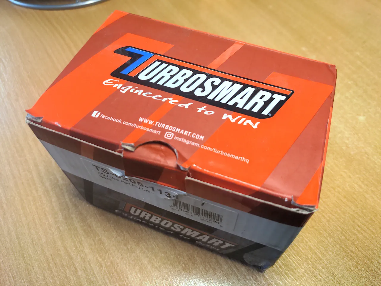
...and replace all of it with a Turbosmart Vee Port Pro instead!! The Turbosmart is V-band-clamped to a weld-on flange, which is compact and looks nice. My friendly local TIG welder took care of welding the flange on.
(I kid about throwing it in the bin; I liked the Bailey BOV too much as a piece of engineering to do that, so I chucked it into one of my "I'll do something with that some day" parts boxes. If you're here from a Web search looking for a Bailey DV26 dump valve for some strange reason, drop me a line! You can have it for the cost of postage.)
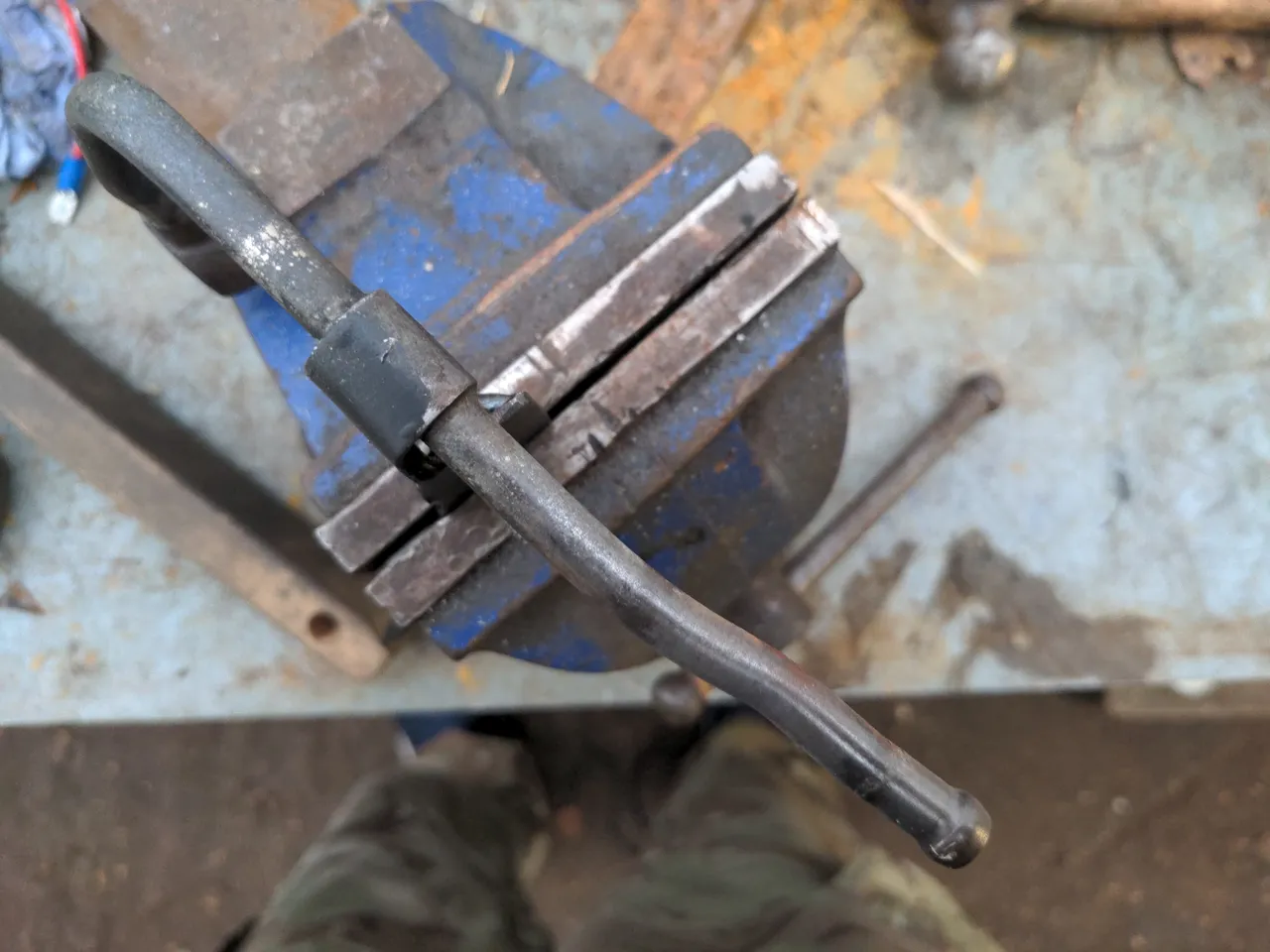
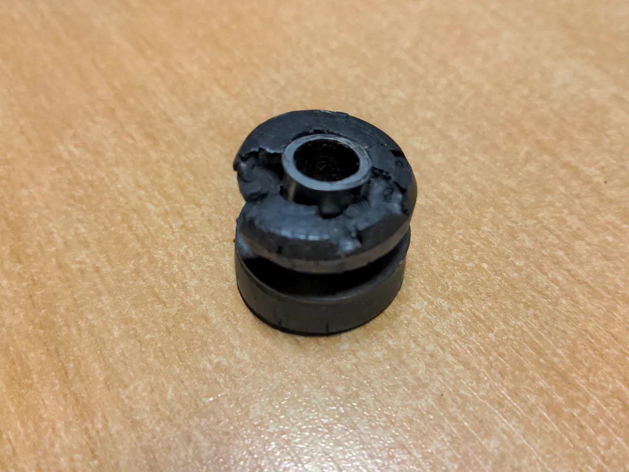
When I stripped the pipe of its components, this mounting rubber fell apart.
I am not blaming the mounting rubber; I prodded it with a screwdriver to make it move, and it fell apart because it is old. I am sure I could have gotten a less destructive result with a more delicate removal technique, but life is short.
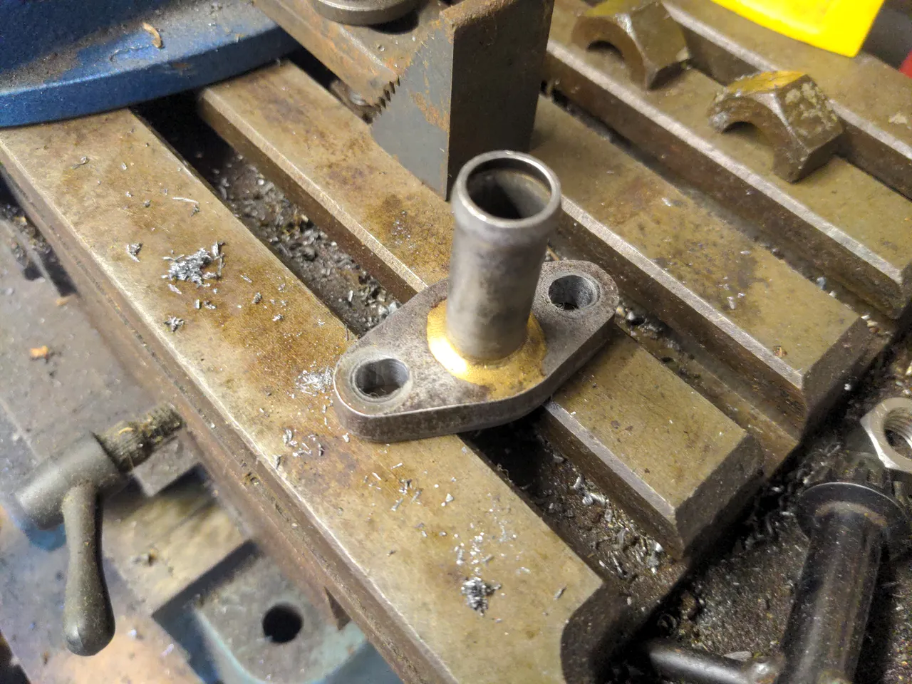
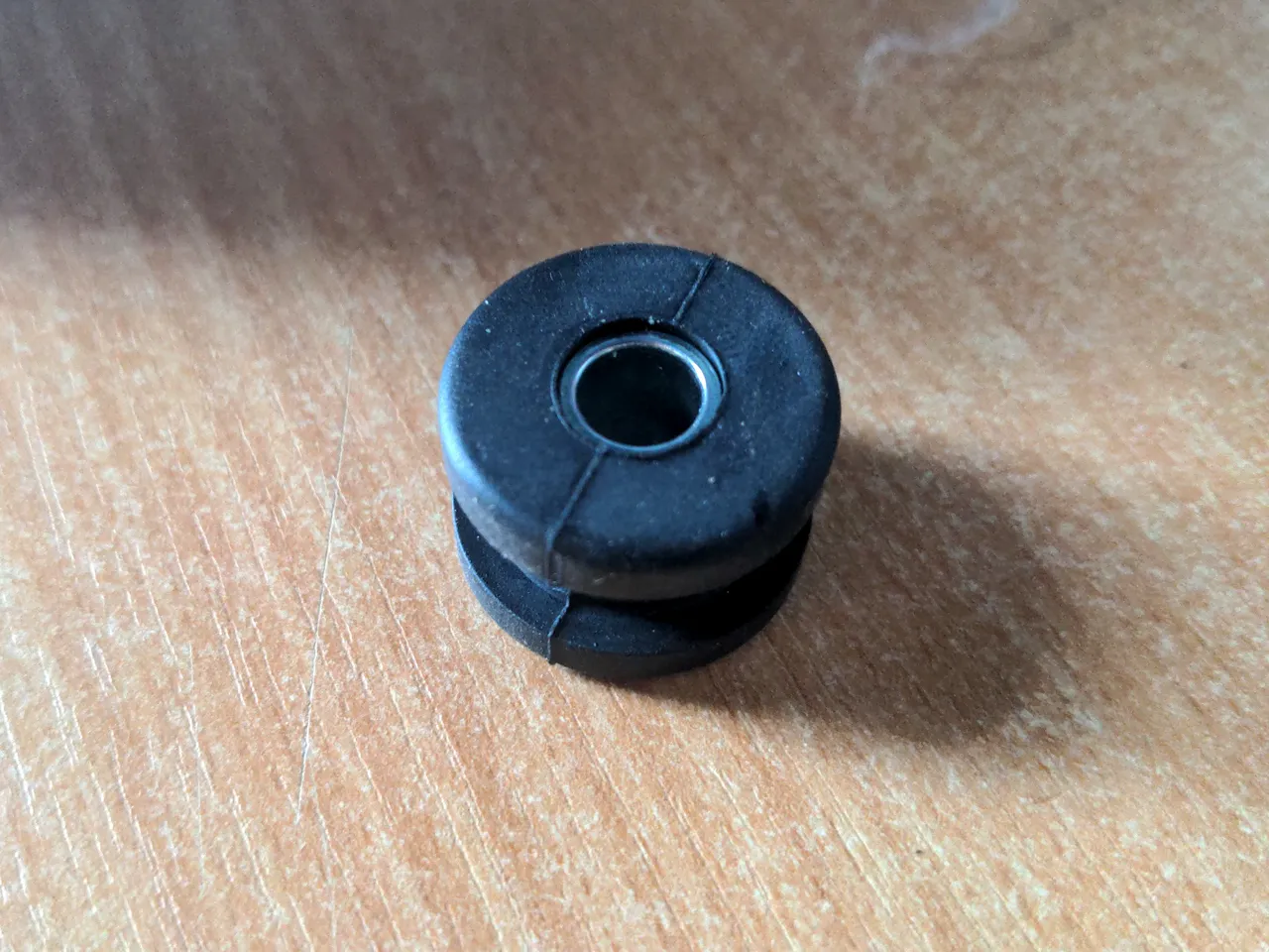
As with almost all GTX-specific parts, these mounting rubbers do not exist anymore. It took an entire evening of eBay searches to work out that you can substitute this with the fuel tank mounting rubber from an early-80s Yamaha TY 250!
It has exactly the same diameters (plural intended) and it is of the correct shape. It is a little bit shallower, so it may require a small spacer underneath it on the engine side to make it fit right. I'll only find out when the engine goes back together.
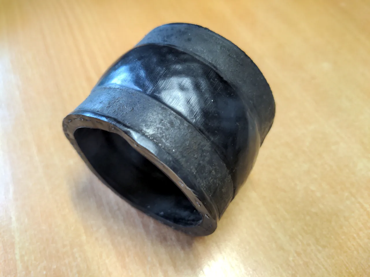
The coupler hose from this pipe to the intake manifold was OK, because it coupled two things together adequately.
But, with everything dismantled, it'd be mad not to replace it and its six-hundred-year old Jubilee clips with something newer and tidier.
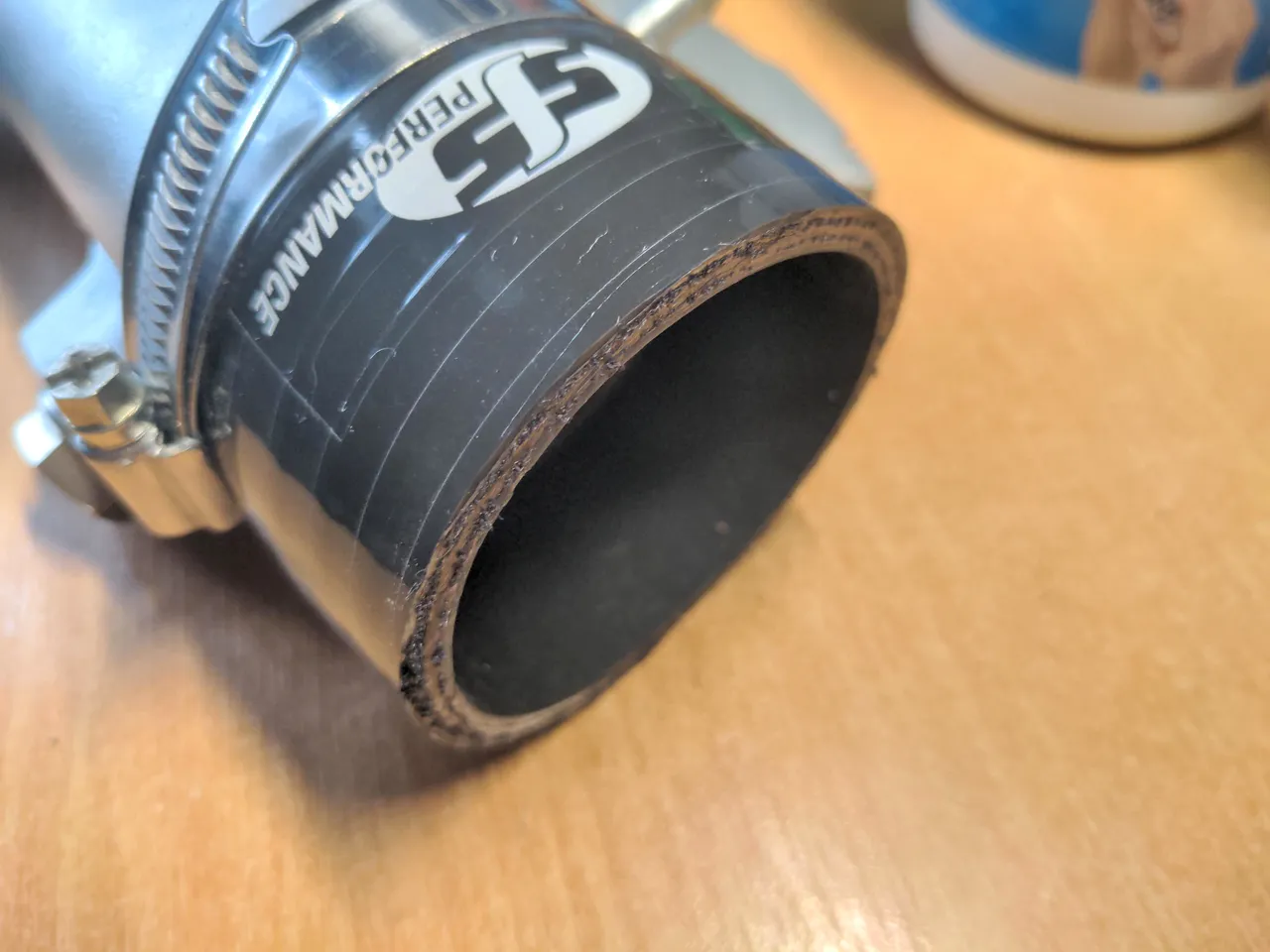
I learned the trick for cutting flexible reinforced silicone hoses like this: Clamp it tightly to a piece of tube using whatever clamp you plan on using when the hose is on your car, then use the clamp itself as a cutting guide. Obvious, isn't it? I am embarrassed that I didn't think of this myself! I got it from a YouTube video.
As it happened, the amount of excess I needed to cut off was exactly two Jubilee clips wide. This made it easier to cut perfectly straight. I clamped it to a piece of exhaust tube and and cut off one Jubilee-clip-width top and bottom, so that the SFS Performance logo was exactly centred along the length.
All the new hoses on this engine will be black, including this one; as I said, I don't like blue hoses. This has an advantage I did not expect. To tidy up the stray white polyester reinforcing fibres that are left from cutting a hose like this, I could burn off the ends with a cigarette lighter and then paint over them with a black permanent marker pen. It looks tidy, though nobody will notice how nice I think this looks.
Oven cleaner, Brillo pads and electrical contact cleaner took care of most of the cleaning. I gave it a coat of very-high-temperature silver paint.
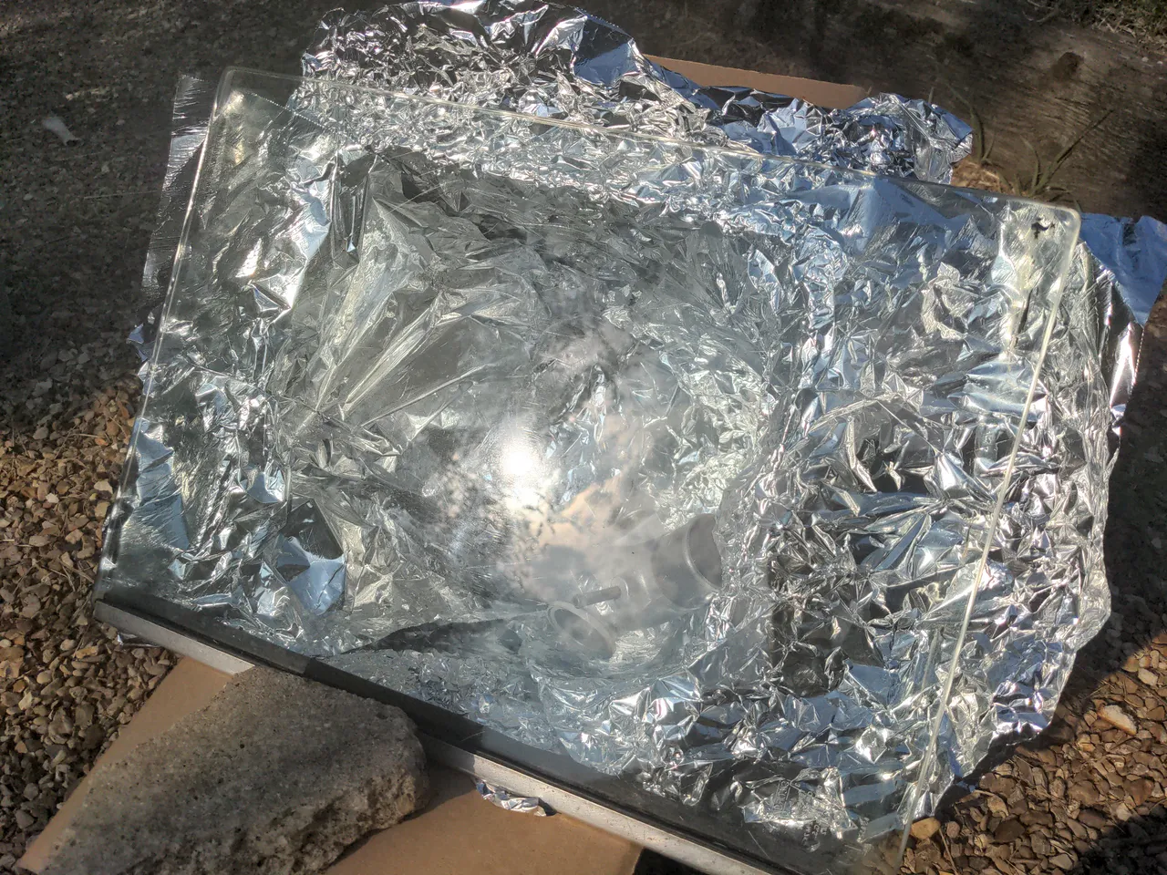
The particular VHT paint I used requires baking to cure it. I did not stick it in the oven, because of our commitment to sustainability and net zero I didn't want my food to taste of VHT paint for weeks. It was a boiling-hot day, so I improvised a solar oven using a box lined with baking foil and a sheet of glass.
We'll see how well this works, when the paint does or does not fall off. It got very hot in there over the course of a day; the unpainted areas of the part were far too hot to handle without gloves when they came out. I don't know if it reached the 160° C required for the paint to cure fully, or if any temperature short of that would be sufficient. Time will tell.
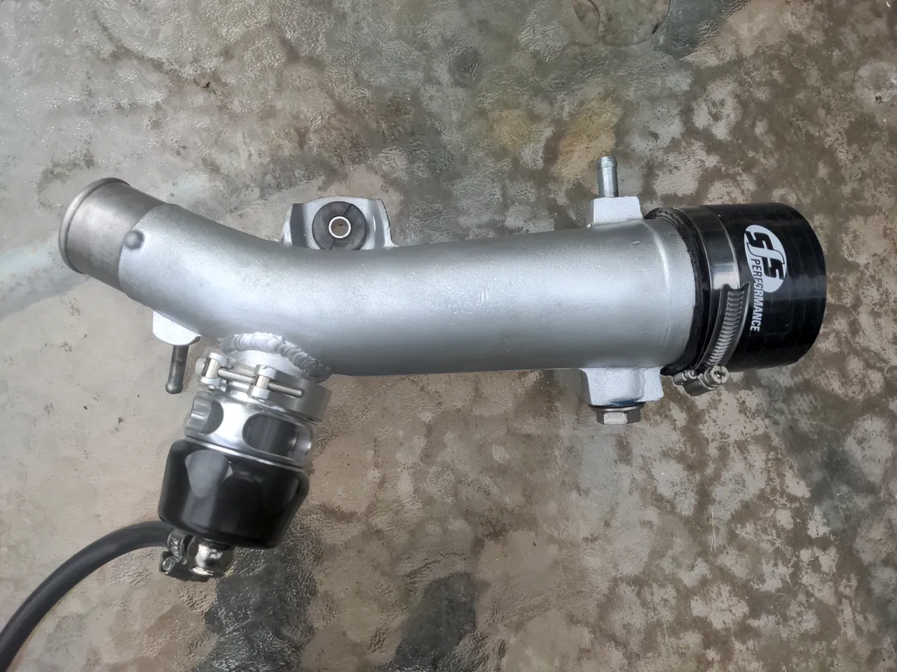
It makes more sense now, and it looks a lot nicer. It was probably more effort than it was worth to take something that already worked and make it into something that still worked, but it does not offend me now.
The next part of this series is unwritten. It involves a half-year odyssey to acquire a new turbo. And I still didn't get a new turbo, as such. I will write that part when some other components that do not currently exist come into existence. So that, is a story for soon.
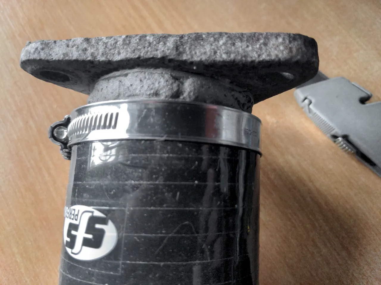
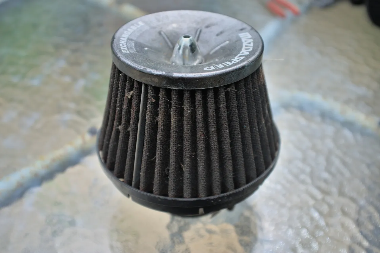
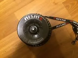
It has "Mazdaspeed" written on it. This would be kind of cool, but Mazdaspeed never made a generic 3 inch cone filter like this. There was, however, a company in the early 2000s taking generic 3 inch air filters and putting the names of manufacturers' performance divisions on them, along with fancy-sounding text like "EXS" and "EXCHANGEABLE FILTER SYSTEM". You could get one with NISMO written on it, if you wanted.
The dialup-friendly resolution of all the pictures I could find hints at how old this filter is...
That is OK, because with a clean and an oiling this would probably remove particles from air as effectively and sound as loud as any other cone filter. It goes into the "badly modified" category I spoke of in the first part of this series because of how it was attached to the air flow meter. (Actually, it should go into the "badly modified" category because this setup sucks hot air straight from the engine bay and as such is probably less effective than the stock airbox, but I digress...)
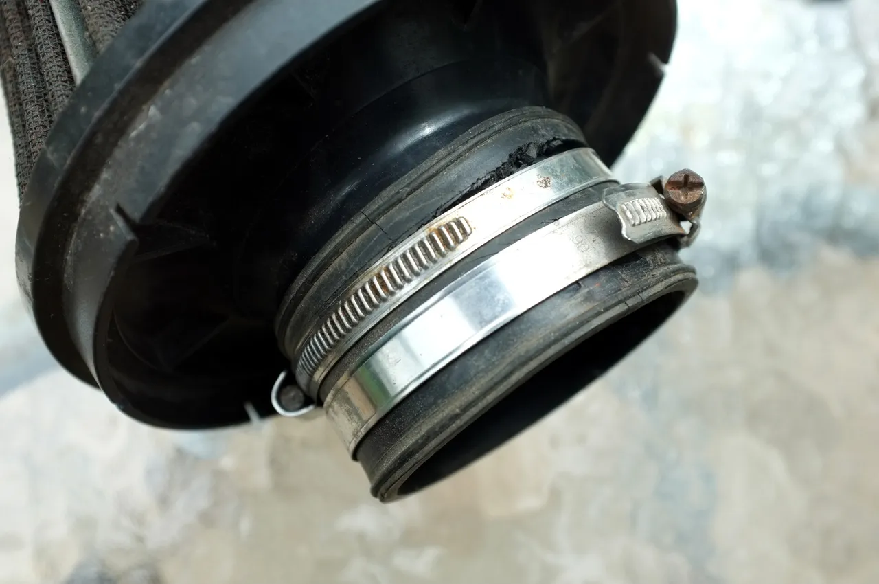
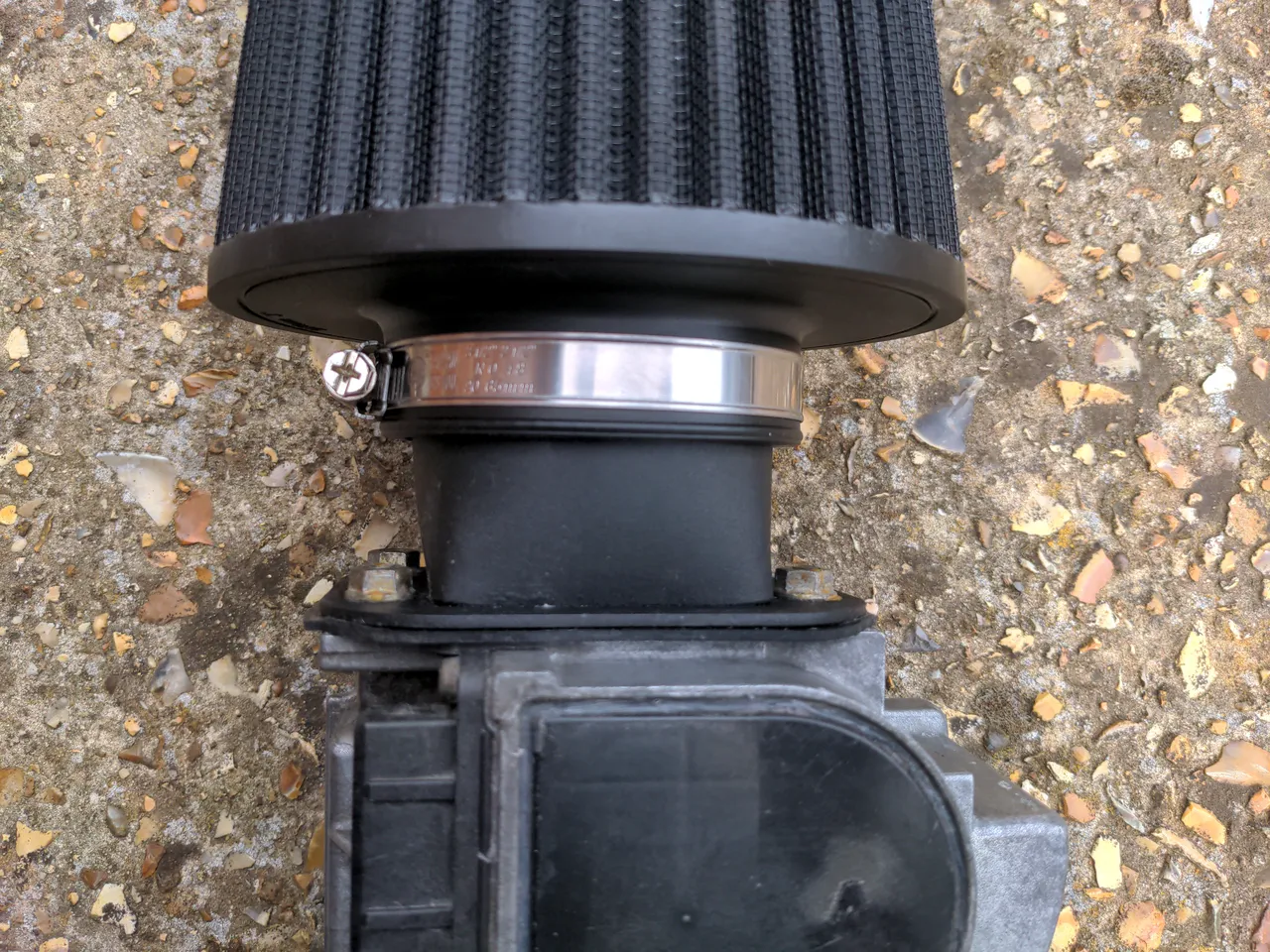
There was an adapter on the air flow meter made of two parts that didn't fit smooshed together to make something that somewhat worked:
As the splitting of the rubber coupler hints (also the fact it kept falling off), this did not work very well. It was mostly through good will and fortune that it never disappeared altogether. This wouldn't do, so I set about designing a new, better, single-piece air flow meter adapter for any standard 3" air filter, spent quite a few hours on some meticulous measuring and initial CAD work...
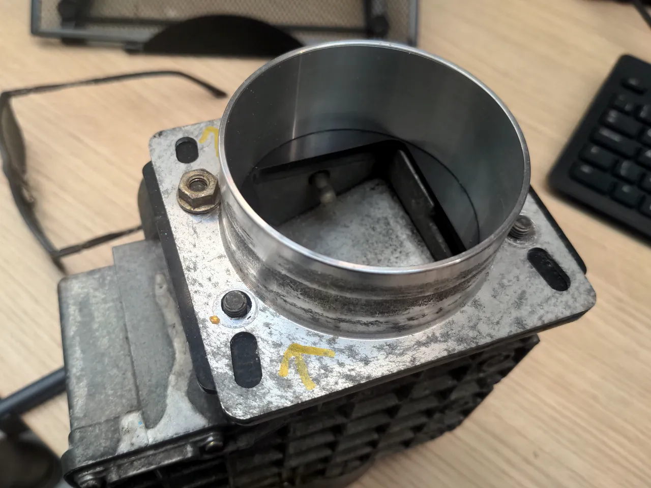
...then found out that I could buy such an adapter off the shelf for about 30 quid. So I did that instead! It was only available off-the-shelf, unlike almost everything else for this car, because the 323 GTX shares an air flow meter with the early 1.6 litre Mazda MX5s. There are trillions of those still on the road, and there is a very healthy aftermarket for them.
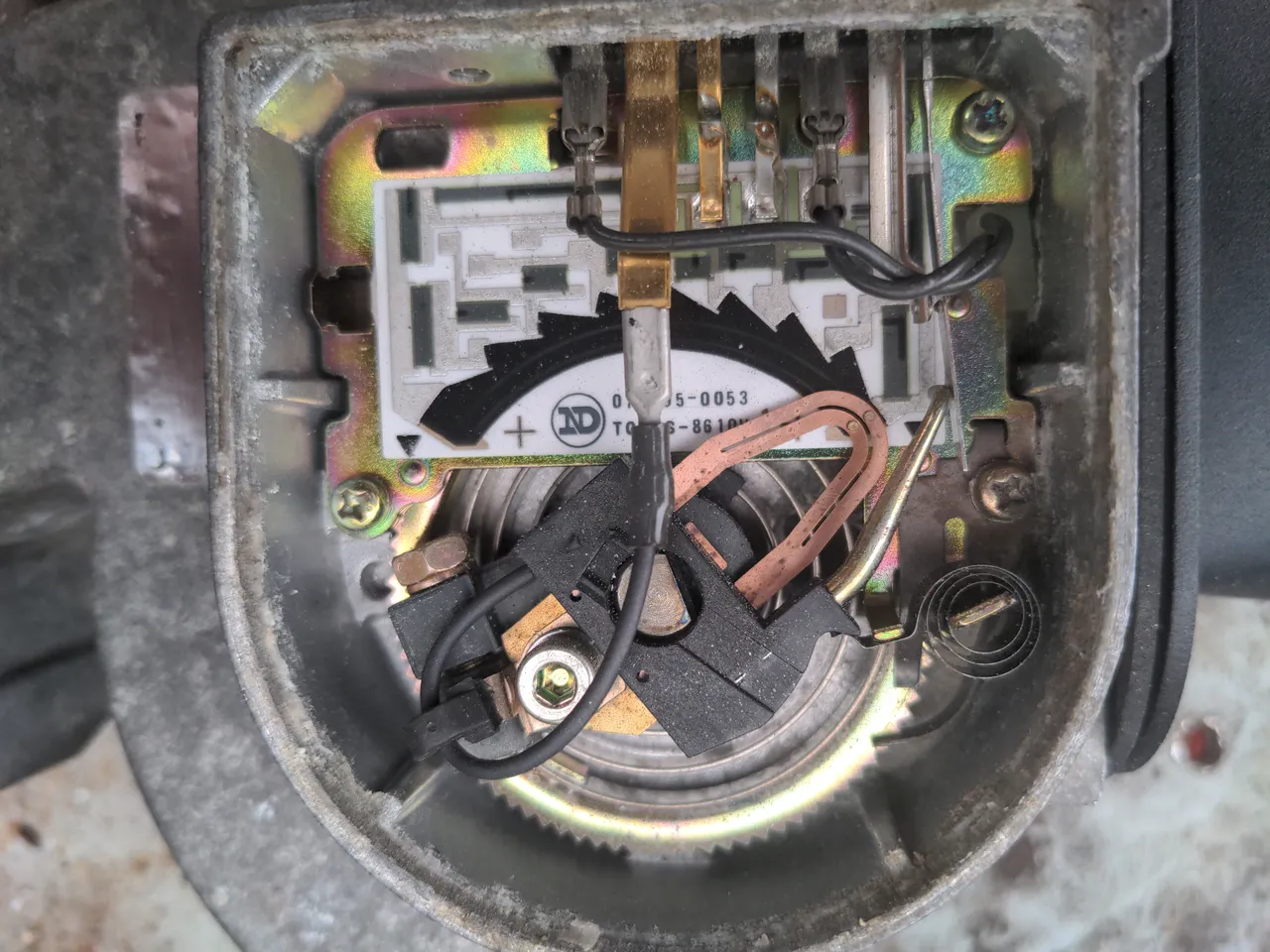
While handling the AFM, I noticed that the vane seemed stuck, which certainly wouldn't help the car run properly. After pulling off the cap, it turned out to not be the most common problem with these air flow meters. Because that was not the problem, chances were that a sharp prod would probably get the vane unstuck. It did! So I gave everything a blast of electrical contact cleaner (nectar of the gods), gave the hinge a little bit of WD-40, and it worked freely and squeak-free after that. I sealed the cap with silicone sealant this time around, because the previous person who took it apart neglected to do that.
I took a photograph of the internals when I had it apart, in case anyone wondered what that looks like.
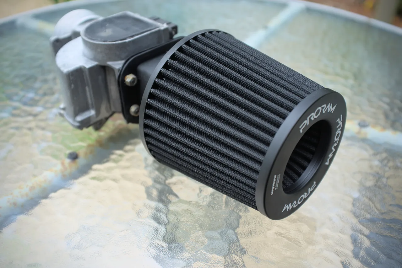
I gave the exterior of the AFM a good clean with a Brillo pad. It did not come up shiny, but it did remove some of the surface corrosion and crust. It now has a PRORAM universal 3 inch filter attached to it, because that was quite cheap, not blingy like the really cheap ones, and will work exactly as well as any other cone filter. The whole assembly looks much neater than it did.
And that, to make a short story long, is that. It was all very easy and I don't know how I got six hundred words out of that! Next up, though, things get a bit more involved...
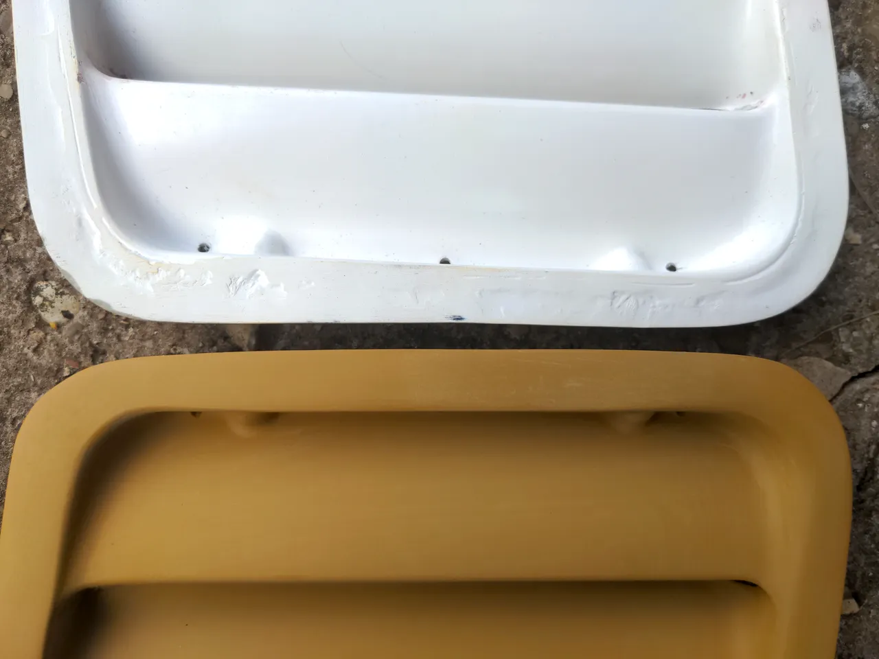
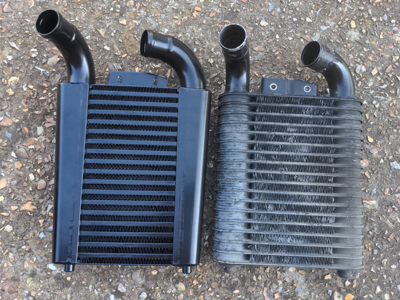
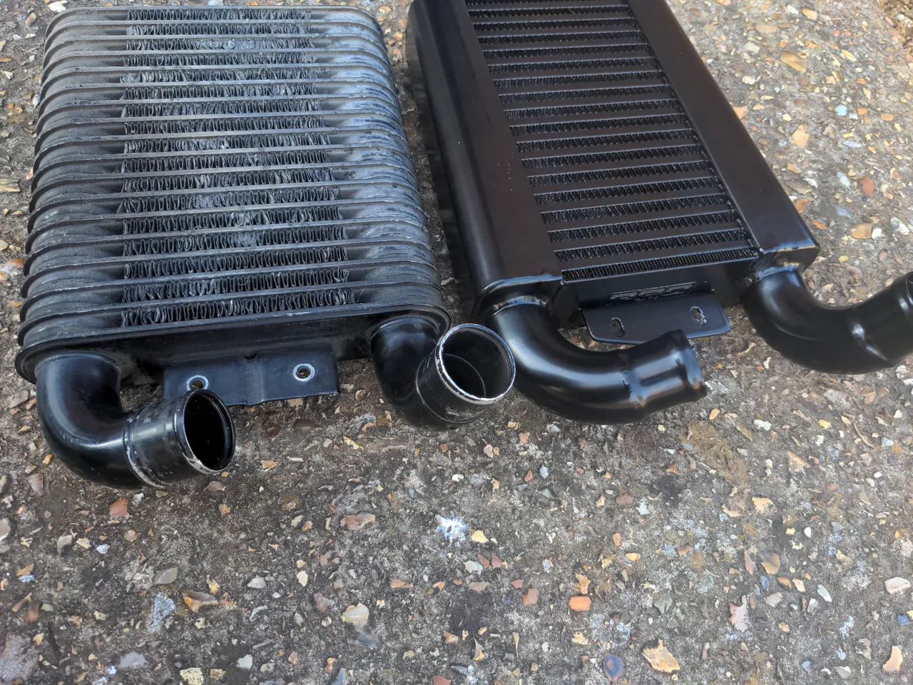
This is my 323 GTX's new intercooler, next to its original one. The new one is a work of art with a 60mm core made by Pro Alloy. The original one is old, weird and inefficient.
So, the Mazda 323 GTX is not dead or abandoned. I put it in warm dry storage, because if I had to look at it every day after the engine's near-death experience I probably would have stripped it and scrapped it. I intended to get back to the Mazda after the P5 was done, because I thought I would have the P5 done within a year.
The GTX came out of storage a while back, and is currently having its engine rebuilt. Someone else is doing that for me, but this has also given me the opportunity to rationalise some things around the intake side of the engine. Some of it is merely old. Some of it has been badly modified over the years, and needs re-modifying in less bad ways. I would never get around to doing all of this if i was still using the car, so maybe the engine death was an expensive blessing in disguise. I have called this "rationalisation" in the title of the post, as if there was anything rational about owning a 1980s rally car that you can't get any parts for.
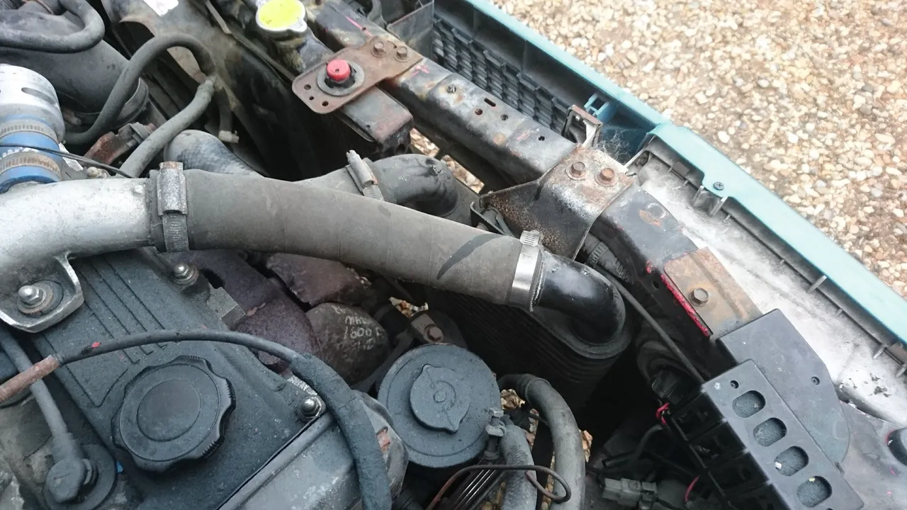
One of those things is the intercooler. It is in the "merely old" category. It used to fit like this in the car:
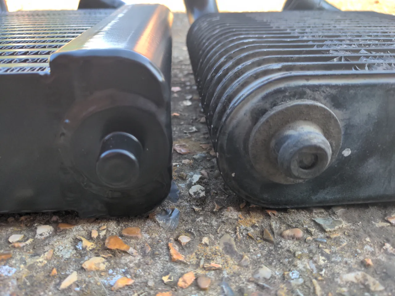
The 323 GTX's intercooler is an old, bad design. This can be forgiven, because this was 1987, and to my dismay 1987 was 36 years ago. It likely did not do very much, but it didn't do very much just as well as anything else of its era. The bent fins that came with age and from being mishandled means it probably did even less. With my newfound desire for reliability, I wanted to replace it with something a bit better.
A recurring problem of owning old, weird, near-extinct cars is that there is a wealth of information out there, from forum posts written 15 years ago. Someone would have solved a known limitation of your car by finding a simple bolt on upgrade from a car that was common at the time and is now just as extinct as your car is. In the case of the 323 GTX, it was an easy bolt-on upgrade to its intercooler with a bigger, much better-designed one from...a first-generation Ford Probe or Mazda MX-6. Well then!
(Digressing, my favourite in that genre was trying to find seats for my mum's Suzuki SJ 410. All you needed to do was pull the seats out of a Suzuki Swift GTi! They bolt right in!)
The obvious solution would have been to go with a big front-mount intercooler. I did not relish the possibility of chopping anything up to mount one (like the unobtainable-at-any-price front bumper). Neither did I want the hassle of reworking all the pipework. I'm going to have to do some reworking of it anyway, because of a different turbo (more about this soon), but a completely different configuration is effort.
I don't know that there would be other complications I cannot foresee with an FMIC setup, because I cannot think of any. I also do not know that there will not be any complications because I cannot think of any.
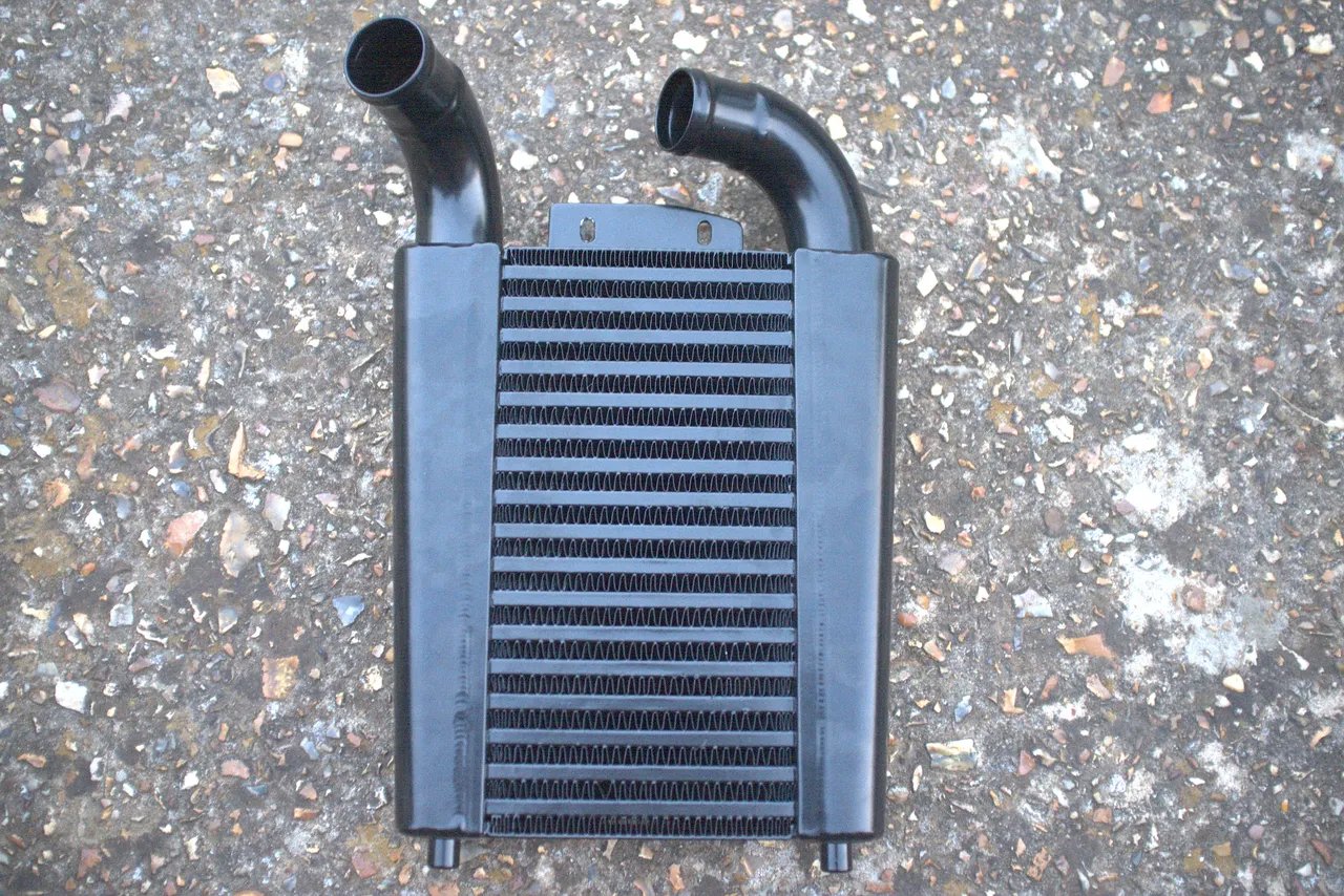
What I wanted was a modern, efficient intercooler which fit in the same space as the existing one. This did not exist, until Pro Alloy made one for me.
The new intercooler is spectacular. It is a much better design, and the quality of the work is impeccable. It came with a price tag that would seem expensive, if you did not price in the fact that I was paying professionals to design something that didn't exist before and then hand-make that thing to the highest standard.
It has been designed to fit in the same space as the original intercooler, using the same mounting points. The pipes are of the same size, and come out in the same place. The height and width of the intercooler does not exceed that of the original at any point. It is somewhat thicker, but the cunning part is that this thickness has been engineered to extend into the engine side, where there is room, rather than into the front panel, where there is none.